Beginner's Guide

Beginners Guide Part 12: Special Focus Layout Themes

Some modelers build their entire model railroad focused on a common theme.  To help a beginner get an idea of this type of model railroad, brief descriptions of three such themes follow.  Those themes are Narrow Gauge Railroading, Logging Railroads, and Early Rail Railroads.
 

Section I: Narrow Gauge Modeling

There is something about narrow-gauge modelling that gets in your blood. It's hard to define just what is. It may be the beautiful mountain scenery for the 3' narrow gauge railroads set in the Rocky Mountains such as the Denver and Rio Grande Western, the Rio Grande Southern or the Colorado & Southern to name a few.


For Maine 2' narrow gauge it may be its top-heavy, quaint, backwoods nature. Quite a number of narrow gauge lines are favorites. Yet there are quite a number around the country: The East Broad Top, a coal hauler in west central Pennsylvania, the Tweetsie or the East Tennessee and Western North Carolina and the many logging railroads prevalent in the Pacific Northwest and other regions.
 
That narrow-gauge railroads have a smaller gauge and proportionally smaller equipment, is what gives it a quaint, grass roots feel. The engines, mostly steam, remind us more of large pick-up trucks servicing the communities along the line than the huge semi-tractor trailer rigs analogous to mainline standard gauge railroads taking goods across the country.
 
Although narrow-gauge modeling remains a small percentage of total modeling population, narrow-gauge modelers make up for it with enthusiasm and highly skilled modeling. Some of the high-level modeling comes from the lack of ready-to-run models requiring the modeler to scratch build his or her cars and locomotives.
Fortunately, that is not a requirement anymore. There are many manufacturers of narrow-gauge equipment, be it 3' gauge, or some of the smaller gauges such as 30" gauge or 2' gauge.
 

HOn3 scratch-built logging caboose in progress.
 
Now let's get more specific about scale and gauge. Scale refers to the ratio between any linear dimension on a prototype item to the same linear dimension on a model of that item.  HO Scale has the ratio of 1:87.  So, for instance, the length of an HO model of a 40' boxcar will be 1/87th of the length of the car in the real world.  40 feet is 480 inches, so the real car is 480 inches long.  Its HO model would be 1/87th of that or about 5.5 inches long.  (480 divided by 87).  Gauge on the other hand refers to the distance between the rails on the tracks.  In the real world that has been standardized to 4' 8.5”.  That is 'Standard Gauge'.  If on your model railroad, you place the rails closer than a scale 4' 8.5", you are modeling in 'Narrow Gauge'.  In the real world, there are examples of railroads with their rails spaced at some really 'odd' distances.  For instance, one logging railroad in Pennsylvania had its rails spaced 46” apart.  Why that distance?  Who knows?  Luckily back then, the major (and some minor) locomotive manufacturers were happy to accommodate whatever gauge the owner wanted.  By far, the most commonly found narrow gauges were 3', 2.5'(30"), and 2'.
 
Often a narrow gauge railroad would lay some 'dual gauge' track – especially if they interchanged with a standard gauge railroad.  Dual gauge track consists of three rails – the outer two spaced at 4' 8.5" (standard gauge), and a third rail in between spaced at their 'narrow gauge'.


Narrow gauge modeling exists in all major scales: HO (1/87), S (1/64), O (1/48) and F (1/20.3) which runs on No. 1 or "G" gauge track (1 3/4" gauge). There is even some 3' narrow gauge equipment for N scale. HOn3, which is the shorthand for HO scale, 3' narrow gauge, (the small "n" means narrow gauge), has a wide following with affordable cars and equipment from a variety of manufacturers.  Blackstone, a division of Sound Traxx has a lot of D&RGW and RGS equipment and even some East Broad Top hoppers.  Micro-Trains has some nice Colorado & Southern equipment. On30, is O scale narrow gauge with a slight compromise in gauges. The "30" is for 30" gauge, a little bit smaller than 3', (36") but a bit larger than 2' (24") gauge railroads, but the cars and engines available include those which model the popular 3' gauge lines such as the D&RGW and other equipment which is patterned after the Maine 2' gauge lines. Bachmann is one of the prime suppliers in this size.  Take your choice. Sn3 has been a popular but more expensive size because much of the equipment is handcrafted in brass. Peter Built Locomotive Works, PBL for short, is a key manufacturer. Much of the original G gauge equipment was semi-scale and offered by LGB, a German manufacturer. This was followed some years later with scale equipment, which operates on G gauge track as 3' narrow gauge by Bachmann and Accucraft.  As these models are quite large, they are somewhat more expensive than HOn3 or On30 equipment.
 
Narrow gauge track and switches are readily available for the most popular scales.  A search through the websites of such manufacturers as Micro Engineering (ME), Shinohara, Peco, San Juan, LGB, and Accucraft AMS should give you a good start- depending on your scale.
 
In the real world, narrow gauge rolling stock tended to be not only narrower, but also shorter and not as tall.  This can be seen in the accompanying picture of two HO Scale gondola cars.
 
On the other hand, there is no difference in size between an HO standard gauge structure and an HOn3 structure.  It is only the locomotives and rolling stock that were smaller in overall size.  That makes populating your Narrow-Gauge railroad with structures as easy as if you were modeling standard gauge.


So why do modelers try to scratch the 'narrow-gauge itch'.  It is probably a combination of the locations these railroads frequented and the industries they served.  They often ran in the mountains or the woods, and served such industries as logging and mining.  You would find them in and around quarries, slate pits, and clay works.  They were prevalent in an era that seems simpler and ripe for research.  And, we might say that the locomotives and rolling stock were almost 'cute'.
 

Section 2: Logging Railroads


Logging can become the focus of a basement filling model railroad, a side branch on a smaller model railroad, or even one module in a modular railroad.  If you have limited space, picture a 2' x 6' shelf layout in HO Scale with a smaller saw mill at one end (with or without a log pond), some logging taking place in the middle, and a small Furniture Mill (Stave Mill, Clothes Pin Factory, Kindling Factory, Box Factory, Hub Factory, etc.) at the other end.  Now picture a small Porter type locomotive shuttling a few cars back and forth.  That could be your 'starter railroad' all by itself.
 
Don't want to dip your toe into 'narrow-gauge'?  No problem.  There were many logging railroads that were standard gauge.
 
Don't want to buy one of the geared locomotives (Climax, Shay, Heisler – or even the rare Dunkirk)?  No problem.  Many logging railroads used rod locomotives from small 0-4-0's to 2-8-0's.  (The little 0-4-2 in this photo, taken at the 2015 NMRA Convention is a good example.)


How about a Forney style locomotive?


Scale?  You have many choices.  Logging structures, locomotives, and equipment are readily available in most of the popular scales.
 
What is that you say?  You are not familiar with some of the wood industries mentioned above?  What in the world is a 'Hub Factory'?  For that matter, what is a Dunkirk locomotive?  Well, one of the other things that draws model railroaders to the logging theme is the joy of the research.  Just go to your favorite search engine and have at it!
 
Now you are relatively new to the hobby or you wouldn't be reading the Beginners' Guide.  But here is a not-so-well-kept secret.  Most model railroaders do not enjoy ballasting track.  Not at all.  Well, logging railroads did very little in the way of ballast, and certainly did not maintain well contoured roadbeds.  A quick clearing of the forest floor, throw down the ties, leave them un-ballasted or just throw forest floor debris between the ties.  Why worry?  That hill up ahead would be cleared of wood soon, and those tracks would be torn up and re-laid elsewhere.


Look at this picture from one of Tom Taber's books on the "Logging Railroad Era of Logging in Pennsylvania" and used with permission.  Look at the flat contour of the roadbed and the 'junk' between the ties.  Now look at the buildings – wood.  Unpainted wood.  Why paint, those are only temporary structures.  Ever want to try your hand at scratch building, but were afraid that the results might be a bit 'crude'?  Well they would be great in a logging camp.
 

Structures

If you decide to model a logging railroad, you could include the nearest town as part of what you model.  It would include stores, housing, a school and a church or two.  Or, you can limit the focus of your modeling to a saw mill and associated structures.  Your choice.
 
Saw mills varied in size.  Some of the smaller ones were one storey tall and had the steam engine in an attached or adjacent structure.  Mid-size and large mills were usually two storeys tall with the mechanisms driving the saws on the lower level.
 

These photos were also taken from Tom Taber's books on the "Logging Railroad Era of Logging in Pennsylvania" and used with permission.


Kits to build saw mills – both large and small - are available in most scales.  Once installed on a model railroad with scenery all around it, a saw mill can become a focal point of the entire scene as the following two photos illustrate.  The fire photo, the one with the slash burner in the background, was taken on Doc Patti's On3 Winged Foot & Western RR.  The second photo was taken on Tom McInerney's HO/HOn3 Elk River RR.  (Both photos taken by Bruce DeYoung, MMR®)


In addition to the saw mill, you might want to add some housing for the mill workers and a store where they can purchase their necessities.  Many logging companies, like many mining companies, provided both of these “amenities”.  In the case of the housing, all the houses had a common design.  Company stores varied in design, but a covered porch the full length of the front of the building was common.  The following two pictures illustrate these structures.


The Company Housing picture was taken on Ted Pamperin's HOn3 Railroad and the Company Store picture was taken on Bruce DeYoung's HO scale RR.  Both pictures were taken by Bruce DeYoung, MMR®.


Rolling Stock

Another appeal of modeling a logging railroad is the variety of interesting rolling stock often found in use.  Much of the rolling stock was built or modified on site, and thus was unique to the railroad.  The following pictures are all located on Bruce DeYoung's HOn3 Slate Run Railroad.  Almost all are scratch built.
 

Log Car
 
The logs are made from branches from a Mountain Laurel bush.
 
Below: A flatcar with bulkhead ends added in the 'backshop' carries a load of pulpwood.  The wood load is again made from Mountain Laurel branches.


A scratch built HOn3 Water Car
 

Scratch built logging caboose behind a Forney locomotive
 

Videos and On-Line Resources

Section 3: Early Rail

Early Rail is a name coined by aficionados to mean railroading before 1900, or at latest, before World War I.  The period 1890 to WWI was one of transition from small locomotives with a limited number of wheel arrangements, wooden rolling stock, and many small railroads, to large regional systems.


This period has an appeal to modelers interested in the history of railroading, the development of technology associated with the railroads, early industries, and the sometimes-quaint look of the equipment.  There are some practical reasons for modeling the pre-1900 period.  The equipment was small.  Locomotives generally had four to six driver axles.  The average car body was only 28 to 34 feet in length and even shorter for the decade after the American Civil War.  For a given a length of track one can fit almost twice as many cars from the 1860's as compared with the 1960's.
 
Limited space for a layout tempts the builder to scrimp on radius size and neglect smooth transitions from straight into curves.  Early motive power and cars allow for smaller radii.  A 4-4-0 heading up 28' cars looks and runs just fine on 20” radius track.  Even early passenger equipment can look good running on small radius track as long as the builder uses smooth transitions in track.
 
Trains often tended to be short, or at least do not look unrealistically short with a small number of cars.  This means yard tracks, passing tracks, and mainlines can be shorter, again a savings in space.


Similar to the twentieth Century, there was a variety of car types.  Some were more commonly seen back then compared with – for example - the 1950's.  Stock cars appeared on many railroad rosters before 1900, but declined in numbers after the early 1900's and were run on few railroads by the end of the Twentieth Century.  With no plastic pellets to be shipped and grain transported loose or bagged in boxcars, there were no covered hoppers back then.
 
Early rail has its challenges, most noticeably the limited range of locomotives, rolling stock and educational material.  For this reason, much of this section looks at sources for appropriate equipment and information.  Modeling early railroading requires some compromises, especially at the beginning when the modeler want to get trains running.  But the challenges can push the modeler into new areas of knowledge and skill, perhaps another plus for Early Rail.


Motive Power

Much of the appeal for modeling the early days of railroading is the steam locomotive, whether gaily painted in multiple colors or a workaday black and Russian iron.  Four wheel arrangements dominated the railroad scene in the latter half of the Nineteenth Century. Before the Civil War the most common wheel arrangement was the “American” or 4-4-0.  Mountainous railroads had developed other wheel arrangements to battle gravity, such as the 0-8-0 “Camels” of the Baltimore and Ohio. The  2-6-0 and 2-8-0 wheel arrangements could be seen in small numbers, but the leading pair of wheels was rigid.  The first 2-8-0 with non-rigid leading wheels was apparently designed by the Lehigh Valley Railroad in 1866 and named the “Consolidation” because at the time the railroad was incorporating a number of smaller lines.  The name stuck.  It was suited for pulling heavy freight trains.  The 2-6-0 “Mogul.” was developed about the same time.  The 4-6-0 or “Ten Wheeler” was used often as an all-purpose locomotive, suited for both fast freight or passenger service, depending on driver diameter.
 
All of these types are available on the new or used market in HO.  They might require some reworking to make them appropriate for the decade being modelled, but certainly acceptable to the modeler wanting a general look.  Bachmann sells a couple versions of the 4-4-0 that appear to fit the 1870's and 80's; the newer version runs well and looks good.  Bachmann also manufactures more modern Americans appropriate to the post-1900 period that could be used as is or back-dated a decade.
 

Bachman Locomotive pulling a kit-built LaBelle passenger car
 

Athearn Locomotive pulling B.T.S rolling stock built from kits
 
Athearn sold a 2-8-0 consolidation based on a Baldwin prototype that has features of the 1890's, although the pilot appears to represent a later decade.  Out of stock at the time of this writing, the models are available from dealers online.  Bachmann makes a 4-6-0 representing a post-1900 locomotive that would be a good stand-in for the 1890's, especially if the Walschaerts valve gear was removed or replaced.
 
In N scale, Bachmann offers a 4-4-0 of the 1870's-80's and Athearn a 2-8-0 and 2-6-0 similar in appearance to their HO models.  In O scale, mid- and late-century Americans are available in toy train and scale versions from manufacturers.
 
In the United Kingdom, locomotives of many wheel arrangements and prototypes are available from manufacturers such as Hornby, Dapol, and Bachmann in several scales. For those interested in the early days of railroading, Hornby has released models of Stephenson's Rocket and passenger cars in OO (1:72) scale.
 
Older, out of production models can be obtained at train shows and online, including Americans and Ten wheelers.  Many of these are about 10% oversized, reflecting tooling of several decades ago when larger motors were the rule.  The modeler using anything smaller than code 100 rail should be aware that many models of European make had oversized wheel flanges.
 
The small locomotives of the Nineteenth Century can be found in brass manufactured several decades ago.  Prices can often be reasonable, especially if needing new paint or small repairs.  Some run well, others need work, including new motors.  Many never left their boxes.
 

34' cars built from LaBelle (left) and Bitter Creek kits
 

Rolling Stock

Typical freight cars around the time of the American Civil War and the decade following rarely exceeded 24-25 feet in length.  The 1870's brought the need for larger cars in the range of 28-30' in length.  The trend to larger cars led to the 34' car becoming almost a standard in the late 1880's through the 90's, eventually succeeded by 36' cars at century's end.


Car design evolved as well.  Early gondolas had low, one board sides and ends, and developed into high-sided gondolas.  Coal-hauling railroads bought gondolas with drop doors or hoppers in the bottom which also be used for hauling other commodities such as lumber.  The northeastern coal lines would have large fleets of small 4-wheel hopper cars called "jimmies."  By the end of the century wood hoppers had replaced the jimmies and many gondolas.


Hoppers had the advantage of being self-clearing but were unsuited for hauling anything but loose material.
 
Some relatively lightweight freight such as carriages and furniture called for large volume boxcars, as much as 50' in length and in the range of 12' tall.  Many midwestern lines and some eastern lines had fleets of these cars, especially as the Michigan furniture industry took off at the end of the century.  Often owned or leased by individual manufacturers, these cars were sometimes painted to be rolling billboards.


This was the period of the fast freight lines, representing cooperative arrangements among otherwise competing railroads.  These were largely ordinary boxcars, but they were often painted with distinctive lettering, heralds, or colors.
 
Passenger cars also evolved in style and length.  The clerestory became ubiquitous on American passenger cars, the so-called “duckbill” roof of mid-century giving way to the “bullnose” roof.  Colors changed from light colors such as straw yellow, to a dark brown, to a dark green.
 
Available models include a limited number of ready-to-run flats, gondolas, stock and boxcars in HO scale.  Bachmann makes a 34' boxcar apparently based on a Missouri Pacific prototype.  Models representing older, shorter cars are readily found at train shows but are generally out of production.  Similarly, a wider range of passenger car lengths and style show up regularly for sale.  Some modelers improve the looks of ready to run models by replacing oversized door hardware and scraping off and replacing molded-on grab irons.


A good option for creating a varied fleet of reasonably detailed models is to build kits. The selection available to the modeler includes most types of freight cars in the second half of the 1800's, including box cars, flats, gondolas, jimmies, stock cars, refrigerator cars, tank cars, and passenger cars.  The modeler can find boxcars, flats, and gondolas in HO, S, and O scales.  The boxcar can be purchased in 25, 28, and 34' lengths, in the case of the smallest cars with a round or peaked roof.  The model railroader capable of laying smooth track, creating scenery, and building simple structure kits should be able to build these kits, which come with clear, detailed instructions and are fun to build.  Many are laser kits in which the interlocking components virtually guarantee easy and precise construction. Kits avoid the problems of ready-to-run models of early cars with oversize door hardware and molded-on details.
 
Once you are comfortable building kits you could try your hand at scratchbuilding.
 

The Right of Way

Most of the rules and habits we formed in tracklaying apply to the 1800's. Track built by the large railroads was well maintained and groomed, with substantial ballast. Smaller railroads often built mainlines in a hurry to get trains running and to earn some income before the money to build ran out.  These tracks could be built to a low standard, but if the railroad was folded into a larger one, the first task was track replacement.  The two big differences between Nineteenth Century and modern times was use of stub switches and the size of rail.  The limitation of the stub switch became obvious and few lasted on mainlines much past the Civil War, although they remained in use in yards and lightly-traveled branchlines.  Therefore, the Early Rail modeler can generally use commercially-available track and conventional turnouts.  Where track appearance can be improved is the size of rail.  Code 100 looks oversize and many modelers of post Civil War railroads go to code 83 or code 70.  Even these are oversized but practical.  The modeler can reduce the apparent size by painting the sides of the rail a dark brown to rusty brown color; this is generally good advice in any case to make track look more realistic.  Of course, hand laying track and turnouts is always an option, even for the beginner having the right skills.


Structures

Rules for selecting and buying appropriate structures apply equally to the Nineteenth Century as they do for today, with perhaps a few more restrictions.  Obviously, the march of time creates one of those restrictions; the modeler must be at least a little knowledgeable of changes in architecture and building materials.  Cinder block and poured concrete buildings do not belong in the 1800's.  Brick and wood ruled the day, with both clapboard and board and batten appropriate throughout the period, shiplap wood siding near the end.


Regionalism in architecture was very much part of the visual environment, city and rural.  Some areas are characterized by brick, especially in cities that mandated masonry.  Prevalence of brick or wood in newly settled states depended in part on local building materials; not every area is rich in sand and clay needed for economical brick construction.  Similarly, stone was a rare building material for domestic use outside the northeast before dressed stone became a choice building material for government and commercial buildings and transportation could efficiently move it all over the country.  Although most of us associate board and batten construction with the wild west or backwoods shortlines, it was in fact used frequently in building throughout much of the country, including railroad structures and factories.


Some businesses and industries have changed in appearance or have largely disappeared altogether.  With the rise of Armour and Swift, every city small or large had at least one meat packing plant or distributor, and these seem to have followed the pattern of a long narrow building.  Even small towns had coal trestles or sheds to supply fuel for homes and businesses.


The modeler will find many kits appropriate to the Early Rail time period in both styrene and wood, the job being to select ones that fit a specific place and time.  The best advice is to develop an eye, study photographs of the prototype, and learn.  A good source of information with many examples is:
A Field Guide to American Houses: The Definitive Guide to Identifying and Understanding America's Domestic Architecture by Virginia McAlester and Lee McAlester (1984) or the second edition: A Field Guide to American Houses: The Definitive Guide to Identifying and Understanding America's Domestic Architecture by Virginia McAlester (2015).
 
Nineteenth Century houses and commercial buildings were distinctive in the use of paint.  Information and many illustrations are in the book by Roger W. Moss and Gail Caskey Winkler: Victorian Exterior Decoration.
 
A rich source of photographs, engineering drawings of historical buildings, and other materials is  the Library of Congress digital collections (https://loc.gov/collections/). Some of the larger city, state, and university libraries host regional collections.
The 1893 book by Walter G. Berg, Buildings and Structures of American Railroads: A Reference Book for Railroad Managers, Superintendents, Master Mechanics, Engineers, Architects, and Students is available in reprint and online.
 
Early Rail shares with narrow gauge and logging railroad modeling many of the same features and advantages.  Equipment is small, track can appear to be very casually built, smaller radii are acceptable, and the builder is often driven to researching their area of interest. More can be built in a small area.  These areas always encourage the model to try building kits and perhaps eventually scratch building structures and rolling stock.  These three areas are not at all mutually exclusive.  Indeed some beautiful models of late 19th century narrow gauge logging railroads have been built.
 

Additional Resources

  1. John H. White Jr., 1997, American Locomotives: An Engineering History, 1830-1880 Revised & enlarged Edition. Johns Hopkins University Press, 624p.
  2. John H. White Jr., 1985, The American Railroad Passenger Car. Johns Hopkins University Press, 704p.
  3. John H. White Jr., 1993, The American Railroad Freight Car: From the Wood-Car Era to the Coming of Steel. Johns Hopkins University Press, 656p.
  4. Anthony J. Bianculli, 2001, Trains and Technology: Locomotives. University of Delaware Press, 248p.
  5. Anthony J. Bianculli, 2001, Trains and Technology: Cars. University of Delaware Press, 256p.
  6. Anthony J. Bianculli, 2001, Trains and Technology: Track and Structures. University of Delaware Press, 240p.
  7. Anthony J. Bianculli, 2001, Trains and Technology: Bridges and Tunnels, Signals. University of Delaware Press, 224p.

Beginners Guide Part 11: Tools

The Tools for Model Railroading

In this Guide for Beginners you will be exposed to numerous construction techniques that require the use of tools. If you are already handy around the house or under the hood of your car, you will be familiar with most of the tools we use. If the world of model construction or "Making" is new to you, this primer on what tools you will need and how to use them should be of interest and value. This part of the guide will introduce you to the basic toolbox and present some hints on how to get the tools you actually need without depleting the bank account.
 
Two basic axioms that apply to tools. First, USE THE RIGHT TOOL FOR THE JOB AT HAND. While not all tools are purpose specific or limited in application, a certain number are and misuse will result in either damage to the tool or to the project being worked. The replacement cost of a damaged tool is a cost that should be avoided. Second, A POOR CRAFTSMAN BLAMES HIS TOOLS FOR ERRORS. Take the time to learn how to properly use the tool for the purpose intended. Keep the tool in good shape. That includes periodic cleaning and sharpening, if appropriate.
 
Special Note for NMRA Members: When seeking a source for a new tool, do not forget to take advantage of the NMRA Partnership Program discounts that will save you money on the tools you buy. The discounts will extend your hobby budget and (alternately), by savings, cover the cost of membership. It is a benefit of your membership - please use it.
 

How long is it?

In model railroading, as in all other construction or "Maker" activities, measurements play a key role in creating a proper finished product. There are two primary tools for measurement: a standard ruler or tape measure, and a model scale ruler. In addition, marking lines that are 90 degrees from each other is an essential requirement for many construction projects and a square or set of squares is recommended.
  1. Measuring Tape. An inexpensive 12-foot retractable tape measure is a general-purpose tool that is necessary for the construction of a module, doing bench work layout, or completing general construction measurements. A tape measure with increments of 1/32 of an inch is generally the best buy. Source - hardware store.


  1. Scale ruler. A "ruler" that is scribed for the scale you are modeling will be necessary for most structure and car construction projects. Having a ruler marked to scale saves a lot of time and avoids the math necessary to complete conversions. A metal hobby scale ruler is preferred because you will make a lot of use of it. Source - hobby store or hobby outlet online.


  1. Square. Another aspect of completing layout measurements is marking cut lines that are at 90 degrees (or square) to your baseline. The simple square will allow you to make these marks, but a more advanced design of square will not only allow a more precise marking but will also help in making the desired cut.
While there are any number of square designs on the market place, the machinist square seems to work best for most modeling projects. The specific design of a "thin beam" square has become my favorite because of the utility of use. Source - hobby store or hobby outlet online.


Helpful hint: If you are going to build several modules or do some serious layout framing, you may find a 4-foot long steel or aluminum ruler is a good buy. The longer ruler helps to layout straight lines, makes measuring longer distances easier, and serves as a good straight edge for laying track. Source - hardware store.
 

How do I mark it?

Making a mark to indicate a specific dimension or measured position is as critical to quality construction as the tool used to make the measurement. Most modelers use a pencil as the normal choice of Marker. That may work for most cases but will fall short for marking fine dimensions associated with the layout and for cutting scale structures, cars, and other smaller modeling uses. A standard No 2 pencil line, when associated with a particular scale, can have a substantial width. The question then becomes, how to make a mark with minimum width.
  1. Pencil. If a pencil is what you have, make sure that the point is kept sharp and the pencil is held perpendicular to the material being marked. If you have a choice of pencils, a harder lead pencil (2H, 3H, or 4H) is a better choice. You might also select a 0.3 mm mechanical lead pencil (normally used for drafting) to provide a thinner width line.
  2. Marking knife. Carpenters and metal workers frequently use a "marking knife" to mark measurements on the materials they are working with. The marking knife makes a much thinner impression on the material.


A specially designed marking knife is relatively expensive for a first toolbox and a hobby knife can be a good substitute. Source - Marking Knife, woodworking specialty store or online.
 

How do I cut it?

The correct tool for cutting depends as much on the materials as the nature of the cut to be made. The tools for cutting standard lumber for the construction of a module or layout structure are much different than those used for working with scale lumber, styrene, or kit materials. This guide addresses the scale modeling tools.
  1. Hobby knife. There are knives designed especially for hobby purposes. The blades are smaller, come in different shapes, and are very sharp. At least two knife handles, sized to fit small and larger blades are appropriate. A #1 Handle (Smaller) and a #2 handle (Medium) will work well. As an alternative to the #2, a #5 handle (Large) is a good choice. As for blades, a stock of #11, #2, #17, and #18 will cover most needs. The smaller handle with a #11 blade is used for cutting and is well suited for the draw or pull action.
 
 
  1. The #2 or #5 handles are best for chisel type blades and the pushing action for using those blades. When you go to the hobby store or search online for blades you will find a wide selection available. While it is beneficial to know about all the blades that exist, it is seldom worth the cost of gathering an inventory of the full selection. The one rule concerning blades is to use a sharp blade which means changing blades often. Source - hobby shop.
Helpful hint: Keep an empty soda can on the workbench as a "Sharps" container. Put the used blades in the container. You may also be able to find a purpose-built "sharps" container at your local drug store for a relatively low cost.
 
Helpful hint: You might be tempted to use a standard box cutter or shop knife for your hobby work. It will not serve well for modeling. The blade is too thick and the ability to make small cuts is very limited.
 
  1. Scalpel. If sharpness and fine cutting count in modeling (and they do), you may find the scalpel a good alternative to the standard hobby knife. The scalpel blade is much sharper than the hobby blade and the blade is also thinner.


Consider that the doctor asks for a scalpel and not a Xacto #11 when cutting on people and there must be a good reason for this. If you do select a scalpel, in addition to your #11 hobby knife, do not forget a stock of scalpel blades. Source - hobby outlet online.
 
Note: For modelers new to using hobby knives a word of caution is warranted. The knife blades and especially scalpel blades are extremely sharp and can cause serious injury if not used properly and carefully. When cutting any material, it is best to use multiple cuts applying only a small force. Be patient, don’t try cutting through material with one or two deep cuts - this will almost always end in poor results and possibly injuries. Multiple light cuts will produce better results and is a much safer technique.
 
  1. Straight edge. To make clean straight cuts you will need a cutting guide or straight edge. The temptation is to use your scale ruler but that will certainly result in damage to the ruler. A better choice is a purpose-built metal straight edge which can be found at an art supply store or hobby tool supplier.


The 12-inch tool is the better choice for general hobby use. The square, discussed in the measurement section, may also serve as a straight edge for cutting. Source - artist supply shop or hobby outlet online.
 
  1. Cutting mat. Your model railroading career can end very quickly if you leave the kitchen table or desktop with several cut marks from your work, so using some form of cutting mat is essential.


A "self-healing" cutting mat is the preferred work surface. A 12 x 18-inch mat is a good choice for the beginner because it will support most projects. Source - hobby store or craft store.
 
  1. Scissors. There will be many instances when a pair of scissors will be necessary to complete a project. A sturdy candidate would be a pair of Fiskars Amplify Mixed Media Shears. They do it all. Source - craft store.
     

Scissors – FISKAR Amplify Shears on top
 
  1. Saw Blades. You may find a need for a hobby sized saw. If so, look to a razor saw that will fit in your #5 knife handle. Select a blade with a thin kerf (thickness) and a high tooth per inch count. Unless there is a need for deep cuts, select a blade with less cutting depth. Razor saw blades, even with a backing sleeve can bend easily and once bent, are useless as a saw. Try to make your cuts as "pull" cuts rather than "push" cuts. Source - same place as knife handles and blades.
     

Saw Blades (Notice Hobby Tool Handle)
 

How do I get the proper fit?

Most craftspeople, or "Makers", learn through experience that getting a final fit on a first cut is seldom achieved. The reality is, after making the cut, some trimming is always necessary to get two or more pieces to fit together in the manner intended. This results in the two basic rules on cutting; (a) Measure twice, cut once, and (b) Leave a small amount of excess material for trim or sand to fit. Because of the very small dimensions we are dealing with in modeling, these are two great guidelines to follow.
  1. Sandpaper: Most of the materials we work with are amenable to reduction by sanding. The trick is to use the correct grit and to keep the surface being sanded properly aligned. Sandpaper comes in various grits and media. The coarsest grits are normally far too severe for our uses. It is most often better to use a higher number grit (less abrasive) and sand for a longer time. For example, 180 grit or higher will most often serve well. Purchasing a pack of paper with several grits will let you experiment on using paper to gain the final fit. Make sure that the paper is placed on a hard, flat surface and the material being worked is moved across the paper. (The material moves across the sanding media - the media does not move across the material.) Most modelers also find a wood or metal block with square sides (a piece of aluminum angle might also serve well) to serve as a sanding guide. If the piece being sanded is moved tightly along the guide block it will remain perpendicular to the sanding surface. Maintaining a flat sanding surface and a perpendicular orientation to that surface goes a long way toward getting the final fit desire. The best choice for all-around use is Wet and Dry paper type. Source - hardware store.
  2. Sanding sticks.  A developed skill of model railroading is finding alternate uses for common materials. Such is the case for the foam centered Emory board, designed and sold for fingernail care. As with sandpaper, the boards come in various grits. The boards can be placed on a flat surface and the material to be sanded moved across the surface of the board. Because of the foam center, the boards can also be trimmed to size and be used as a sanding stick. In this manner, they serve extremely well for interior sanding of window and door holes. Foam centered Emory boards make good sanding sticks. Source - beauty supply store, cosmetic section of drug store.
     

Sandpaper and Sanding Sticks
 
  1. Files. Some common materials (wood, metal and styrene) can also be finished with a file. The skill necessary to "file to finish" takes time to develop. The most common files used by modelers are jeweler's files and miniature diamond files. The standard jeweler's files work well on either wood or styrene and the diamond files work well on metals. Files are normally sold in sets and, much like knife sets, they include tools not frequently used. A flat file, triangular file, and round file cover most requirements. One specific use for files that rivals the use of sandpaper is getting the final fit on internal openings such as for doors and windows in a model. Source - hobby store, hobby outlet online.
     

Files - Diamond Files on Top
 

Let's lay some track

Elsewhere in this guide, you will be provided some detailed instructions on how to create a "bulletproof" track system. (See Part 4 of the Guide.) To enable you to do that a few tools will be required.
  1. Radius tool or trammel points. Much will be said about curved track and how to maintain a smooth flow through a corner on the layout. Drawing accurate curve radii markings to aid in accurate track placement is key. There are many tools such as trammel points that, when used with a bar or ruler, let you draw an accurate curve. An alternate method is using a homemade radius bar. Start with a piece of wood about 1 inch wide and 3/8 inch thick. Inscribe markings one inch apart along the length of the stick. (A wood yardstick is great for this purpose). Start the markings (point zero) one inch from one end of the stick. At point zero and at the several inch markings suitable for curve radius for your scale, drill a 3/16 inch hole. Now, using a pushpin or something similar, tack the point zero hole at the center of your curve radius and putting a pencil in the correct radius hole, scribe the necessary curve. Source - hobby supply outlet, woodworking specialty store.
     

Trammel Points with ruler
 
  1. Pushpins. If you intend to use cork or similar materials as roadbed, a way to hold it in place while glue sets is required. A proven method is by use of push pins. When you purchase pins, look for ones with long shanks because you will use them for many other purposes. You will probably use a lot of push pins. Source - craft store.
     

Push Pins
 
  1. Nail setting pliers. To hold the track in place while allowing adhesive to set or while applying ballast to the track, small steel nails are normally used. If you are using "flex" track or sectional track, those track pieces come with small holes drilled through the ties to accommodate the nails. The key is to set the nails deep enough to hold the track in place without damaging the plastic ties or deforming the track. The common tool used to set nails is a set of needle-nose pliers or design-specific "nail setting" pliers.
A good choice are parallel jaw pliers that allow one to hold the nail firmly and press straight down to set the nail. Regardless of the tool you choose, practice with some scrap track to get the "feel" for how much pressure is required and how to tell when the nail is set. Source - hobby supply outlet. Source – hobby supply outlet.
 

Pliers for Setting Track Nails – Needle Nose and Parallel Jaw
 
  1. Rail Nippers. Unless your track plan is designed specifically to use only 'sectional' track, cutting track to size will be required. Two tools of choice are the Razor saw (see above) or the purpose-designed rail nipper. While looking like a side cutter or dyke pliers, rail cutters or "nippers" are a specially designed tool. The blades of the cutter are flat on one side so the finished cut is also flat. This is important to achieve close-fitting joints between track sections. RAIL CUTTERS ARE NOT WIRE CUTTERS AND SHOULD BE PRESERVED FOR THEIR DESIGNED PURPOSE. Get the correct model of cutters for your track scale and follow the instructions for alignment of the tool for cutting rail. WEAR SAFETY GLASSES WHEN CUTTING RAIL WITH NIPPERSSource - hobby shop.
     

Rail Nippers
 

Track Laying Tool Set
 
  1. Tools for Joining Rails.  Mechanically connecting the ends of rails is done using "rail joiners" which slide from one rail to the other. However, the task requires the modeler to exert a "push" force on one end of the joiner while maintaining alignment of both of the rail ends to enable the joiner to slip onto the second rail. Any number of specific design tools have been created to enable this seemingly simple task, but few meet the challenge. Most modelers use smaller needle-nose pliers, a small standard tip screwdriver, or a cuticle stick. Try them all to find the tool and method that works best for you. Source - hobby shop, hardware store.
     

Rail Joiner Tools
 
  1. Soldering iron. A common practice in track laying is to solder the individual rail sections to each other at the joiners. How best to control the alignment of the track will be addressed in the tracklaying section of this guide. To complete soldering you will need a suitable soldering iron. An iron of 35 to 45 watts will meet the needs for HO and smaller scales. A larger iron may be required for larger scales. If you can find an iron that has replaceable tips, that may be the better initial purchase option. Also consider a solder iron with a digital temperature readout, as well as one that will turn itself off after some time not in use. Source - hardware store, hobby shop, online.
     

Soldering Iron
 

Soldering Iron Stand
 

Soldering Iron with replaceable Tips, Stand and Digital Readout
 
  1. Soldering tools. A stand or holder for a hot soldering iron is essential. Laying a hot iron on the work surface is a sure invitation for damage or personal injury. Solder is required and the common choice is a 60/40 tin/lead mixture. Lead-free solder is available and, if you intend to work with electronics, lead-free will be the better choice. Because cleanliness is essential to a good solder joint, a mechanical cleaner (scratch brush) and a chemical cleaner (flux) are recommended tools. Many modelers find a tool to hold things in place while soldering to be useful and there are sets of simple soldering aids available. After the solder has cooled, it is good practice to clean the residue flux from the joint area and cotton swabs and isopropyl alcohol are the standards for the task. Source - hobby shop, electronics supply house.
     

Soldering Tools - Scratch Brush, Wire Holders, De-solder Tool
 
  1. Rail cleaner. A common problem with operating layouts is that the rails tend to accumulate dirt and "crud" over time and require cleaning. Several different tools and methods for cleaning rails and keeping them clean are available. However, doing the initial clean (or cleaning after a longer period of non-use) calls for a different tool. The cleaner of choice will remove the accumulation of "gunk" without excessive abrasion or pitting to the track or disrupting track alignment. A good tool for this task is the track eraser, a silicone block with a very fine abrasive mixed in. There are other purpose-built track cleaning tools. A common cork will also clean track. Source - hobby outlet online.
     

Rail Cleaning Tools
 

Getting Power to the Rails

In both DC (Direct Current), an analog power system, and DCC (Digital Command and Control), a digital power system, passing electrical power from the source to the track requires some electrical wiring. The tools required for this task, in addition to some already addressed, are reasonably standard. Wire sizes used in wiring a layout can vary in size (gauge) and hence the capacity of the tools selected may vary. For example, wire cutters required for a 12-gauge power bus will need to be more stout than cutters needed to handle 26 gauge feeder wires. The choice of specific tools may be driven by your modeling scale.
 
  1. Wire cutters. DO NOT USE SPECIALLY DESIGNED RAIL CUTTERS (covered previously) TO CUT WIRE. The most common tool for cutting wire is the diagonal cutters or "dykes". They are available in various sizes and selecting a pair that will handle the largest gauge wire to be used is a good choice. Source - hardware store.
  2. Wire strippers. The wire that is used in modeling, either solid or stranded, will be enclosed in a sleeve of insulating material. The tool designed to cut away the insulation is the wire stripper. The proper selection is one that will handle all gauges of wire to be used.
     

Wire cutters (two images on left) and wire stripper (image on right)
 
  1. Because strippers for smaller wire do not normally allow the cutting of larger gauge wire, two tools may be required. Wiring a layout requires many electrical connections and the stripper will be a much-used tool. Select wisely and learn how to use it with scrap wire. Source - hardware store, electronics supply outlet.
Drill and Bits. The electrical connections to the rails will be on the top of the layout while the actual wiring runs will be under the table or the underside of the modules. This arrangement requires that the track feeder wires be passed through the layout tabletop materials. The tool required is a hand drill or smaller battery-powered electric drill and bits slightly larger than feeder wire diameter.
 

Hand Drill and Small Battery Powered Drill
 
If the layout base is thick insulating foam board (Blue board or Pink board), a piece of wire of the proper diameter to pierce the full thickness of the foam must be used. Source - hardware store.
 
HINT: consider a battery-powered electric drill that will also be useful for household jobs.
 
  1. Electrical joint insulation.  The wiring running under the layout will include many locations where feeder wires are joined and normally soldered to the main power buss wires. Those joints must be insulated to prevent short circuits. The two most common means of insulating are liquid tape or heat shrink material. Liquid tape is applied over the entire electrical connection area and allowed to dry. It is important to make sure that the joint is sound before applying the liquid tape because it does not remove easily. Heat shrink, either tape or tube, is placed over the joint and then heated to "shrink" the material around the joint. DO NOT USE A SOLDERING IRON TO HEAT THE HEAT SHRINK MATERIAL; IT WILL PROBABLY DAMAGE THE SOLDERED JOINT. DO NOT USE A STANDARD "HEAT GUN" AS IT WILL DAMAGE YOUR WIRING AND OTHER WORK MATERIALS. A good heat source for reducing heat shrink material is a miniature heat gun designed for use in rubber stamp making and other crafts. An alternate is a common hairdryer. Source - craft store, hobby outlet store.

What tools and materials do I need to construct scenery?

Creating the visual empire on the top of your layout, called scenery, will require a variety of tools, depending on what materials you use. While the market place is full of appealing implements, the cost of the items, and the ability to use less expensive alternates should be considered.
  1. Cutting Foam. The introduction of insulating foam board, in varying thicknesses for scenery use, has resulted in several tools to cut foam. Most of the tools involve a thin heated wire that melts the foam to complete "cutting". These tools work well, and each design has pros and cons. If you do choose to purchase a foam cutting tool, one that is a single cutting wire (similar to a wand) may be the most useful design. Again, learn how to use the tool by practice on spare foam. Practice making the kinds of cuts you will use in creating your scenery. An alternative to the hot wire tools is the fillet knife.
     

Fillet Knives are Useful Tools for Cutting Foam
 

The thin blade of the knife permits good control of the cuts.
 
A thin blade serrated edge knife is also a good choice. Keep the edge sharp. Source, Hot Wire Cutter - hobby shop. Source, Fillet Knife - thrift shop.
 
  1. Shaping Foam. Once cut to a basic shape, the foam is normally worked on to give it a more realistic appearance or shape. The tools preferred for that effort are the Sureform tool (a very rough-cut file like tool), and a selection of picks or scribes. The Sureform comes in several sizes and the one that has a small head and a comfortable handle is the most common choice. The picks used are normally either discarded dental picks or common automotive repair picks. Source - hardware store.
     

Sureform tools
 
  1. Using Hydrocal.  Still in common use, Hydrocal (a modeling plaster) demands some different tools to be used properly. The first set of tools are those needed to repeatedly mix batches of the plaster. Because Hydrocal, when set, is very strong and hard and is not easily removed from utensils, picking the correct tools is important. The mixing bowl of choice is rubber so the bowl can be flexed to remove the dried residue from each mix.
     

Rubber mixing bowls
 
There are several rubber bowls offered but a suitable substitute is half of a discarded basketball. To complete mixing, a selection of inexpensive plastic mixing spoons is the best choice. Source - hobby shop, thrift shop.
 
  1. Plaster Application tools. Getting the mixed plaster from the bowl to the layout and placed, as desired, requires both hands and, usually, some type of brush. HYDROCAL IS HYDROSCOPIC AND WIILL EXTRACT MOISTURE FROM YOUR HANDS IF NOT PROTECTED. The use of protective gloves is appropriate. While latex or nitrile gloves will work, the common rubber gloves for kitchen use may be a better choice. They are more durable and can be reused numerous times. The rough texture of the gloves makes it easier to grip wet items and even aids in spreading the plaster by hand without leaving a smooth hard surface which does not look natural. Spreading wet plaster on the surface can also be achieved with a paintbrush. The most inexpensive bristle brushes serve well. Plaster sets quickly and if not washed off immediately, will permanently damage the brush. Source - hardware store.
  2. Other scenery tools.  After the basic scenery base is established, the finishing process is normally a series of steps involving paint, stains, and materials such as ground foam. Painting normally requires brushes for application and the specific media used and the manner of application determines brush type. A common factor is keeping the cost down. Less expensive throwaway brushes are preferred. Stains and adhesives require some kind of spray bottle. Having several bottles at hand, each for a different liquid is a good practice. Clean the spray mechanisms frequently. A bottle that sprays a mist is very handy for applying the topcoat to the finished scenery. Ground foam or similar scenery materials are normally spread over an area of the layout using some sort of shaker container or a small kitchen strainer. Shaker bottles are available or can be made to fit the need. One tool, while not common to most layout construction efforts but which is very useful, is a common hatchet style Ionic hairdryer. The key to dryer selection is to get one that applies heated air to the scenery surface at low flow rate so the scenery material is not blown away. Source, Spray Bottle - left over household use, beauty supply store. Source, Hair Dryer - thrift shop.

Building Structures and Cars

One of the challenges and enjoyments of our hobby is to create an environment in which our railroad serves a purpose. That will normally include the presence of structures and rolling stock to provide destinations and the means by which goods can be transported via our railroad. Options for obtaining these include buying things already made, constructing structures from kits, or creating items from raw materials (scratch building). The art of construction (kit or scratch building) requires some additional tools not previously discussed.
 
  1. Sprue cutter. Plastic kits come with the various pieces and parts attached to a "sprue", a waste part of the casting process, which links the pieces together in the mold and provides the flow path for the hot plastic to the individual parts in the mold. Removing the individual pieces from the sprue without damage or need for major additional finish work is the job of the sprue cutter. These tools are normally available in either plier or tweezer form. DO NOT USE A SPRUE CUTTER FOR ANY OTHER PURPOSESource - hobby shop.
     

Sprue Cutters
 
  1. Tweezers. The one tool that you can apparently never have too many of is tweezers.


They are available in all manner of designs and sizes. Several tweezers will be useful, and their selection should be based on their ease of use and fine point design. Since the object of tweezers is to pick up, position, and hold items, these should be the guiding criteria for selection. Source - hobby supply outlet online, craft store, beauty supply outlet.
 
  1. Clamps. For items being joined so that they remain in the correct place while the adhesive sets, some type of clamp is normally required. Selection of clamps with a universal application is a good idea.


Plastic clamps are not normally used with plastic models since the solvents used to “weld” plastic together may also weld the clamps to the model. For the same reason, wood clamps are not used with wood models. A good selection of clamps will include some bar clamps of the correct size, some spring clamps, and some C-clamps. Some modelers have enjoyed success using hair clips and rubber bands as clamping devices for smaller items. Source - hobby shop, hobby supply outlet online.
 
  1. Angle blocks. For construction, the ability to achieve square corners and plumb (perpendicular) sides is critical to producing a quality product. There are many tools available but one that serves very well is the angle block. Two basic designs are available. The simplest is one that looks like a piece of angle iron with the adjacent sides finely milled to a right angle. The second is the 1-2-3 block with all six sides milled to precision and all sides at 90 degrees to the adjacent sides.
     

Angle block and a 1-2-3 block
 
Both designs allow the model sides to be clamped in place at a 90-degree angle to each other and plumb while the adhesive sets. They need to be cared for to protect the surfaces and cleaned periodically to remove any accumulated adhesive or other foreign material. Source - hobby supply outlet online, machinists supply house.
 
HINT: For modeling with wood, LEGO blocks can be assembled to create a very stable and accurate square corner guide. Source - LEGO store, toy store.
 
  1. Paintbrushes. Unlike the brushes recommended for scenery work, a set of fine, higher-quality artist brushes will be required for painting and weathering models. Start simple and go with better quality rather than the lowest price.
     

Assorted paint brushes
 
It is a good idea to have a couple of the more common brush sizes and shapes (detail, general painting, highlighting, etc.). Get brushes with bristles appropriate for the paint you use. A good brush cleaning tank and drying stand are useful. Use the correct cleaner for the paint in use and have additional cleaning tanks, as necessary. Source - craft store.
 

But How Do I Actually See My Work?

Being able to see your work is of paramount importance in our hobby, especially when adding fine details and painting small parts.
  1. Light. The first means of improving vision is to provide more and better light on the subject that we are working on. There are many different lamp designs for static and portable lights for use on the workbench or the layout and no specific guidance is required. However, there are two recommendations to consider in selecting lights. First, pick a light that will be easy to use and to focus on the area of interest. A portable high lumen lamp works well for the layout or work bench. A good high energy headlamp is also very useful for working under the bench or work that requires two hands. Being able to point the light right where you are looking minimizes frustration. Second, if the light is required for painting models, use the same type of light that will be used to display the model when finished. The color shift that occurs with different types of light (light frequency/wavelength) will change the appearance of a model when you move it from the workbench to the layout.
  2. Vision Assistance. Enhancing vision, even for those with very good eyesight, is common for close-up and detailed work.. A common method is to use an optical enhancement visor or Optivisor headband magnifier. This tool comes with several different lenses and may include attached light sources. Another way to enhance vision is to use increased diopter glasses, normally sold as "reading" glasses. Select the enhancement factor desired and use the glasses, as appropriate. A more recent addition to the field is the optical device employed by dental hygienists or similar professionals. The head lamp is a central LED light and adjustable loupes mounted to an eyeglass frame. They provide the vision enhancement you want and light where you need it but these tend to be quite expensive. Source - hobby supply outlet online, drug store.

Making sure that it will work

One of the most frequently used but overlooked tools is the NMRA Standards Gauge. This is a simple pressed steel device that allows the modeler to check if track is in gauge, wheels are in gauge, that there is proper clearance around the track, and that coupler heights are correct. The gauge also allows a check of the various dimensions associated with the correct functioning of turnouts and crossing. To detect problems with trucks on cars the gauge supports measuring wheel flange dimensions and wheel tire widths. If there are mechanical problems on a layout or operating equipment, the NMRA Standards Gauge is one of the most important tools needed to find the answer. An NMRA Gauge of the proper scale is essential. One with the enhanced clearance sleeve is even better. Source NMRA Store online.
 

NMRA Standards Gauge
 

Your own toolbox

This completes the discussion of the tools most essential to entry into the hobby. As you read through the Guide and carry out the various processes described, you will encounter recommendations about additional tools that you might need. Over time, and with experience you will add to your toolbox. You will also find alternate safe uses for some tools and find others that have little or no utility for you. Rarely will you find a tool that has no practical use. Your continued development of skill in the use of your tools will result in an increased quality in all your modeling activities.
 
                     FIND THE RIGHT TOOL FOR THE JOB AND HAVE FUN!!!

Beginners Guide Part 10: Weathering

Why Weather?

Why, as a beginner should you worry about weathering your models?  For that matter, why should any modeler take a perfectly fine model and make it look weathered?  Good questions.
 
Let’s tackle the first question first.  Why should a beginner learn how to weather models?  Because, it is a basic modeling skill.  Additionally, it is actually an easy skill to learn – at least at a beginner’s level.  As for the second question: “Why should any modeler weather a beautiful new model?”  The answer to that is also easy.  Modelers for the most part are trying to create a sense of realism on their dioramas, modules, or model railroads.  A miniature ‘real’ world you might say.  In the real world, brand new vehicles and structures do not stay ‘new looking’ very long.  The sun, wind, and weather are all working against that.


If you look at the nearby photo, you will see a beautiful NYS&W RS-1 Locomotive right out of the box from Atlas.  Beautiful indeed.  If you are old enough and lived in New Jersey in the 1950’s, you might have seen the Susquehanna’s RS-1’s in their silver paint scheme in action.  They were filthy beasts.  They probably only looked like the locomotive in the picture when they rolled out of Alco’s paint shop.  By the time they arrived in the Susquehanna’s yard in Jersey City, ‘road grime’, exhaust soot, rain, etc. had already changed the look significantly.  Now look at the Lackawanna boxcar behind the RS-1.  It shows a modicum of weathering that took about 5 minutes and less than a dollar in supplies.  It doesn’t look like a plastic model right out of the box.  A sense of realism is creeping in.
 
Generic Weathering vs. Protype Specific Weathering
Before going any further, a distinction should be made between ‘generic weathering’ and ‘prototype specific weathering’.  Prototype specific weathering takes a photo of a specific real item – piece of rolling stock, locomotive, vehicle, structure, etc. and then replicates it as closely as possible.   Every piece of rust, every water stain, every smear of soot – you get the idea.  It is really a hobby within our hobby, and there are practitioners whose work will make your eyes pop!  If you ever get a chance to attend a prototype modelers’ meet, do so.  You will not be disappointed.


Generic weathering is not that.  Generic weathering simply wants to make a shiny new model look more weather beaten.   The two photos of the Westmoreland Coal Co. Hoppers are an example.  The weathering on the car was done with a pencil.  The technique will be explained shortly.


Weathering Techniques for Beginners

If you search the Internet for information on weathering locomotives and rolling stock, you might get the idea that you need to buy an air brush and learn how to use it.  Clearly an air brush can be a useful tool for weathering, but there are many modelers with nicely weathered models who have never handled an air brush.  A beginning modeler can do a lot of nice weathering with pencils, chalks, weathering powders, and various washes.  (Weathering powders and washes will be discussed in more detail in a moment).
 
To Spray, Or Not to Spray
Plastic and metal models possess non-porous surfaces that make it difficult for our weathering chalks, powders and pencils to adhere to securely.  On the other hand, wood and cardstock present us with very porous surfaces that aggressively accept those same weathering materials.  So, one warning is to apply those chalks and powders sparingly and carefully on those porous surfaces because once down they will sink into the pores of the surfaces and be hard to remove or blend into the surrounding areas of the model.
 
As for how to help make the non-porous plastic and metal surfaces like our weathering chalks and powders better, there is a solution.  Spray those surfaces with Testors Dullcote (a flat lacquer fixative) or a similar product from the art section of a craft or art store.  Simply look for a flat or matte spray fixative.  These, once dry, provide a little ‘tooth’ to help our powders adhere to the plastic or metal.  They also help hide that 'new model plastic shine'.
 
Some modelers also spray their models with the matte fixative again after applying the weathering powders.  They do this to permanently ‘fix’ the powders to the surface of the model.  This is not necessary on wood or cardstock models, but can be helpful on plastic or metal models, especially if they will be handled a lot.  Just be warned that this second ‘over spray’ will significantly tone down your weathering efforts.  Sometimes they almost disappear and require additional applications of the powders.  When using any weathering powders, pan pastels, anything other than spirit based weathering washes and paints, you can only seal it with artist's fixative as any other spray varnish will make the weathering wash off.  For what it is worth, all of the models shown in this section of the Guide were in use on a model railroad, and none of them received an overspray of fixative after they were weathered.
 
Weathering with A Pencil
When talking about using a pencil to weather a model, we are talking about a pastel pencil.  The ‘lead’ in a pastel pencil feels softer and oilier than a normal colored pencil.  On a plastic model it can be spread and blended with a sponge eye shadow applicator.


If you start with a black two or three-bay hopper car in your favorite scale, you will get satisfying results.  Simply run the pencil along and under the top edge of the car, along the external ribs and rivet lines, and on the sides of the dump chutes under the car.  Then blend with either end of the eye makeup applicator sponge. (The makeup section of a dollar store can be a treasure trove of tools!)
 
After the sponge accumulates some pastel color on it, you can also rub that along the smooth sides of the car where you want some rust or other weathering.  The rust on the Westmoreland Coal car was done with a Conté à Paris pencil in the color Bistre.  If your car is Oxide Red or another color, you might choose a brown or grey pastel pencil to simulate coal dust, road grime etc.  Get a few cheap cars and experiment!
 
Weathering with Powders
As model railroaders, we live in a time of plenty.  There are more weathering products available to us now than ever before.  
  • Commercially Available Weathering Powders
We will not mention any specific brand of weathering powders, but if you do an Internet search for “Weathering Powders for Models”, you will get several pages to sort through.  You could also attend a meeting of your local NMRA Division and get the recommendations of some of the members in attendance.  They will all have their favorites!  Most commercially available weathering powders contain some ingredient that helps them adhere to the surface of a model.


To apply these powders to your model, you can use an assortment of paint brushes of different widths and degrees of softness.  Once used for applying these powders, you should not use them for paints.  They will begin to wear down from the abrasive nature of the powders and their bristles will start to get ragged.  Also helpful in applying weathering powders are Eye Shadow Applicators and Micro Applicators, both equipped with sponge tips.  We have already talked about the Eye Shadow Applicators.  The Micro Applicators can be found in some craft stores and on the Internet.


The girders on the bridge in this photo were weathered with a rust colored commercially available weathering powder.  The powder was applied with a Micro Applicator and lightly blended with an Eye Shadow Applicator.
 
  • Powdered Artists’ Chalks


You can make your own powdered chalks for weathering by taking a stick of chalk and rubbing it gently on a medium sized file.  Unlike commercially available weathering powders, powdered chalk will not contain an ingredient to help it adhere to the surfaces of our models.


Thus, they are most useful on models made of wood, cardstock, or some other porous material such as plaster.  You can store your powdered chalks in small clear plastic containers sold in all craft stores.  The applicators used for powdered chalks are the same as are used for commercial weathering powders.
 
  • Pan Pastels®


Compared to powdered chalks and the commercial weathering powders mentioned so far, Pan Pastels® are a recent arrival on the model railroad weathering scene.  They are not so much a powder as a cake of a soft colored pastel material that feels oily to the touch.  It comes in individual tins, or in multi-colored collections such as the one shown here.  This collection appeals to model railroaders because it contains a number of colors that represent rust, dirt and grime.  (Once again, if you search the Internet, you will find plenty of sources for Pan Pastels®.)


The best applicators for Pan Pastels® are the Eye Shadow Applicator and the Micro Applicator.  Use the first for large areas and the second for getting the pastels into tight corners or small spaces.  In the picture of the Erie RR hopper car, an eye shadow applicator is being used to do ‘generic weathering’ on the entire side of the car.  Notice how it tones down the bright white lettering.  The car had been sprayed with a matte fixative before weathering started.  If all you wanted to do was add rust along the outside ribs on the car, you would use the micro applicator.
 
Weathering with Washes
Washes can be classified by the liquid used to form the wash.  Three of the more popular liquids used are rubbing (Isopropyl) alcohol, water, and Mineral Spirits.  We will look at these three types of washes in the paragraphs that follow.
 
The underlying concept of using a wash as a weathering technique is that a pigment is mixed with the appropriate liquid, usually with a large proportion of the liquid to a small portion of the pigment, and then spread over the surface to be weathered.   The liquid then evaporates with time and the pigment is left behind on the surface of the model.
 
  • Alcohol Washes
As already mentioned above the alcohol used is Isopropyl (Rubbing) Alcohol.  Found primarily in grocery stores and pharmacies, it is usually found in two strengths in the US: 70% and 91%.  Although both can be used when making a wash, these washes are often used on wooden models, and the 91% strength has a lesser risk of warping the wood.  (91% means 91% Alcohol and 9% water.)   A greater strength of alcohol also means quicker evaporation.


The usual pigment mixed in with the alcohol is India Ink.  Black is the dominant color used for weathering, and Higgins is one of the leading brands in the US.  This ink can be found in Craft Stores and most Stationary Stores.  (Windsor & Newton is a popular brand of India Ink in the UK.)  A pigment that is a distant second is leather dye (not leather polish).  We will focus on the Alcohol and India Ink mix, commonly abbreviated as A&I.
 
A good basic mix to start with is 2 teaspoons of India Ink to a pint of 91% Isopropyl Alcohol.
 
Let’s say that you are weathering the wall of a building or the side of a boxcar.  Take a soft artist’s brush, dip it in the mix and flow the mixture down the side of the building or car in the direction that rain would fall off the roof.  It will soon evaporate and leave the pigment behind. More pigment will accumulate along ridges like battens on a building or external ribs or rivet lines on a piece of rolling stock.


This picture will give you a better idea of what we just discussed.  The wall was painted a cream/beige color and then an A&I wash was applied.  See how the pigment is more defined along the vertical battens?  Also note that it no longer looks like a newly painted wall.


On the other hand, if you want to make something look milky white, like the roof of this refrigerated car, you now know how to accomplish it.
 
  • Water Washes
Used primarily on plastic, resin, or metal models, water washes use water with a water-soluble paint or pigment mixed in.  (Using a water-based wash on a wood model will promote warping, and has ever more drastic results on cardstock or plaster models.)
 
Water based washes can be made by taking a small plastic container, adding water, and then adding enough water-based paint of your desired color to obtain the tint that you are looking for.  Washes can also be accomplished by dipping your paintbrush in the paint (just a little) and then dipping the brush in a container of water.  You then brush the thin mix on your model where you want the weathered appearance.


The deck of this tender was weathered by using the first method.  A rust colored water-based paint was mixed with water and then a soft, medium sized artist’s brush was used to flow the mix over the deck. (A good rust color usually consists of a mix of an orangey color with a brown color.)  When the water evaporates, the rust color is left, especially along ridges and rivets.


Here is the second method being used to weather the side frames of these freight car trucks.  The brush was dipped in a rust colored water-based paint and then into a container of water before being run along the trucks.  Once that water evaporates, the rust color will be left in all the nooks and crannies.


The same approach can be used on the outsides of the wheels themselves, yielding these results.  Notice the striking difference between the weathered and un-weathered wheelsets.
 
  • Mineral Spirit Washes
In broad strokes, here are the steps used to weather with mineral spirits:
  • Put a small dab of tube-based artist’s oil near top of surface to be weathered.
  • Dip soft flat brush in odorless Mineral Spirits
  • Draw the ‘dab’ down the surface in direction that water would flow
  • Keep working it until you get desired results
 
 
Here are some of the supplies needed to weather with mineral spirits.  There are now a number of ‘odorless’ or ‘low-odor’ mineral spirits available on the market.  Choose one of those and follow all manufacturer’s cautions for use.  
 
Also get a few small tubes of Artists’ Oils in a tube.  The umbers and siennas are good for simulating rust.  Black is another useful weathering color.  Art supply stores or craft stores should have a selection.


Useful equipment is shown in the photo.  A ceramic container is better than a plastic container since it is less likely to tip over and also less likely to be affected by the mineral spirits.
 
Simply put a little of the mineral spirits into the ceramic container, place a dab of the artists’ oils on the model where you want some rust, dip the brush in the spirits and draw it down through the oils in the direction that rain would run.  The following photos show the process.


Here a dab of artists’ oil paint had been placed in the upper left corner of the wall.  The wall is made of styrene plastic and has previously been painted grey.


Here a soft flat brush has been dipped in the mineral spirits and has been ‘drawn down’ through the dab of oil from top to bottom.  The process has been repeated until the desired look is accomplished.
 
The nice thing about this process is that it can be totally erased – even after a day or two.  Simply apply more mineral spirits and wipe it all off with a cloth.


All the rust effect weathering on this plastic structure was accomplished with the method described above.
 

Putting It All Together

One of the first questions we asked was, “Why weather at all?”  The answer given at the time was to help create a sense of realism.  


Now look at this little scene.  The scratch-built series of sheds as well as the track and detail items were weathered using the techniques we have just discussed.  In each case the weathering technique chosen depended on either the type of surface being weathered (tar paper roof vs. metal roof) or for convenience of application (wash on walls and sides of rails).  Now look at the refrigerated rail car in the upper right-hand corner of the photo.  Right out of the box. It looks unnatural in comparison.


Or compare the two photos of steam locomotives.  Both were made by IHC.  One is weathered using the techniques described above and one is right out of the box.
 
Which looks more ‘real’?  This one, or the one that follows?


So why not give weathering a try!
 

Videos and On-Line Resources

Beginners Guide Part 9: Operations

Background

Many guides for beginners do not touch on the topic of operations.  Perhaps the reason is that the topic can quickly become complex.  However, having some knowledge of operations can be very helpful in how you design your model railroad.  For instance, the location, length and number of sidings, both industry sidings and passing sidings, can be integrally tied into the type of operations you envision.  The same can be said of the number, location, size and design of any railroad yards you want to have on your model railroad.  One type of yard commonly mentioned when reading about operations is the staging yard.  These yards are usually built out of view of the finished portion of the layout and are places where trains can be assembled for later appearance on the finished portion of the railroad during an operating session.  If you are not interested in operations, you would probably not build such staging yards, but these yards are much easier to build as part of the original design of a layout than they are to retrofit later on, so think ahead. Even the type of rolling stock you purchase and run on your layout can depend on your decision to operate your layout prototypically or just 'run trains'.
 

This double ended staging yard located behind the layout allows trains to exit from either end
 
This section of the Guide should provide you with a basic idea of what it means to operate a model railroad as opposed to just “running trains”.  Hopefully that knowledge will also help you design your track plan and select your rolling stock.
 

Introduction

Operations is doing role play - engineer, brakeman, hostler, dispatcher, etc., to bring life to any size of layout in a somewhat prototypical manner. Think of the model railroad as a theater where the trains are the actors.
 
Let’s start with a simple example:


A friend sends you this nicely weathered Saybrook Northern Boxcar to visit your model railroad. You want to send that friend a picture of the boxcar sitting in front of one of your on-line industries to document its time on your railroad. You could, using your fingers, just set the car on the tracks in front of the industry and snap a photo. Or, you could use those same fingers to put the car on one of the arrival tracks in your yard and have your railroad deliver the car to that industry. You will now have to think like the employees of a real railroad think. Welcome to some simple operations.
 
You think for a minute and decide to pull a switch engine from the back of the yard to make up a small freight train to drop off cars at local industries. In the real world, railroads also receive cars that are not going to any industry on the railroad, but rather are traveling through to "interchange" with another railroad. These interchanges happen either at an interchange track or a shared interchange yard. Looking at your model empire, you see a logical route to take to serve those industries and interchange locations. You realize that putting the cars in a particular order will make dropping them off easier. You set your switch engine to work to assemble the freight cars in that order. If you are running your layout in a time period when railroads were still using cabooses, you pull a caboose off the storage track and add it to the end of the train. Once done, you park the train on the departure track, disconnect the switch engine, and park it out of the way. Now you pull up the road engine, connect it to the string of cars comprising your train and pull out of the yard. You start dropping off cars at the local industries and interchange locations in the order you come upon them. This will often require leaving some of the train's cars sitting on the mainline while you drop off the car. You might have to pick up an empty car before dropping off the new car, so think ahead. In due time you drop off the Saybrook car in front of the Craig Brothers Tool & Die Company. In the end, your train will consist of cars you picked up, plus your engine and the caboose. It is now time to head back to the yard since your job is done. Congratulations! You just finished a simple operating session. Along the way, you took on a number of roles: dispatcher, hostler, engineer, conductor, brakeman, etc.
 

You can have a lot of operating fun with a small local freight train
 
If you wanted to make the operating session more interesting, part way through the delivery of your freight cars, you could dispatch a passenger train from the yard to travel over the mainline. Since passenger trains have priority over freight trains, you would have to park your train in the nearest passing siding before the passenger train arrives in your location. Once it passes, you could pull out on the mainline and continue your work.
 
When you get started in operations, remember that it is not about achieving perfection, it is about getting some of the very basics right, like avoiding derailments, stutters and stalls, achieving smooth coupling/uncoupling procedures and ensuring trains move in a realistic manner. Only go to the level of detail, realism, and complexity that fits your comfort zone.
 
If you operate your layout by yourself that is all you have to worry about. You make all the decisions: what locomotives to use, which cars to include on the run, which industries to serve, when that freight train and the passenger train would leave the yard - where they would meet up and when. You get the idea. Now think about doing something similar with two or three operators. Someone in the yard making up trains. Someone else running the freight. A third person running the passenger train. Either a fourth person or one of the first three deciding when the trains should leave the yard, etc. You can see that those visiting "operators" will need to follow some rules and will need guidance as far as which cars to put in the train, which to drop off or pickup and where. They will also need to know how to avoid blocking the mainline when another train needs to get past and even more importantly, how to prevent a collision with another train. Several main techniques have been developed to help make these decisions and address the scheduling concerns. Each of these techniques have many variations made to fit individual model railroads.
 
  • Note: Although operations with visiting operators can certainly take place on a model railroad wired in DC with 'blocks and cabs', in general, operators operating on an unfamiliar layout would find DCC easier to use. So, if you envision operating the layout with several others, especially of there will be guest operators, you might strongly think about DCC. If you plan on operating the railroad yourself, or with a close friend who knows the railroad almost as much as you, then DC could still be an option.
The rest of this part of the guide will give a quick look at some of those techniques.
 

Terminology: Locations and Routes

A model railroad layout when viewed from an operations perspective consists of track, turnouts (switches), and scenery - in particular structures and towns, which provide locations. Each location has a name used to identify it to the train crew, for example in timetables and train orders (more about these below). Examples of locations are: town, station, team track, yard, etc.


Sometimes a location is identified by a sign on a structure and other times by a sign on the fascia
 
One or more locations are joined by tracks to form routes. The train crew take their train along a route, stopping as required to simulate passengers or freight joining or leaving the train, adding or dropping cars to simulate collection and delivery of freight.
 
Locations are typically illustrated on a railroad schematic (track diagram). This can be as simple as a line showing the locations in the correct sequence. Yours will likely be simpler than this: https://tfl.gov.uk/maps/track/tube. It may be more detailed showing the spurs and sidings (for example as required for a control panel): https://www.warwickshirerailways.com/gwr/gwrls3907.htm
  • The schematic is not to scale
  • All angles are 45 degrees
  • It includes the names of the tracks and locations. For a large layout, the overall schematic might have a few location names; it is supplemented by schematics for each group of locations, such as a town​
  • Detailed schematics typically include mileposts. Model railroads will find travel time more useful.


Schematic on Gaylord Gill’s Buffalo and Chautauqua S-Scale RR
 

The Train

Now that we have established locations where trains might stop to conduct 'business' and possible routes to take to reach those locations, it is time to consider the trains themselves.
 
What do trains do? They pick up passengers and deliver them, they pick up many different types of freight and deliver it, they roll along the mainline, they meet and pass other trains on sidings, they interchange cars with other railroads, they get rearranged in yards, they get serviced on "rip"tracks while the engines are maintained in roundhouses and engine shops, they maintain the track with special "MOW" equipment... the list goes on.


In the real world, railroads do not assemble their trains at random. They are assembled with a specific purpose in mind. In the case of passenger trains, this could depend on the day of the week and time of the day for commuter lines, and the time of the year and destination for long-distance train travel. (Longer trains for holiday travel, or travel from a cold climate to a warmer destination in winter, for example.) For freight trains, it depends a lot on what has shown up on the arrival tracks and what customers on line have told the railroad they need. For model railroaders who participate in operations, these issues are handled very often by one of two techniques or a combination of those techniques: Car Cards and Waybills or Switch Lists. There are certainly other approaches, but these two are good ones for beginners to research.
 
Car cards are probably the most common way that modelers use to send cars to their destination. The car card typically includes information identifying the car and can include road name, road number, perhaps color, other description, or even a photograph. The card is folded up to form a pocket that is a bit hard to see in this photo. The waybill indicates where the car originates and its destination as well as any routing instructions. When it arrives at its destination, it is usually turned to the next position and put back in the pocket of the car card.


The train crew carry the car cards and waybills with them as they move the train, leaving and collecting them at each location to match the cars that have been picked up or set out. Layout owners who use car cards and waybills will often have convenient card holders mounted on the fascia anywhere pick-ups or set-outs occur. Since there is a car card for each car in the train, a long train can mean a big stack of cards. While handling a throttle, radio, and a pile of cards, it is easy to drop something, and if it's the cards, you can spend valuable time putting them back in order. Many veteran model railroaders wear a waist apron with pockets to hold car cards and other items.
 

Car cards and waybills being set up for several departing trains in a main yard
 

Switchlists are just a piece of paper with instructions for what to do with a car.
 
The illustration here is for the yardmaster on a particular model railroad. This is only part of a longer sheet that lists cars and their destinations, as a three-letter code. That's enough for the yardmaster to sort them into the right tracks to build an outbound train. Note that it does not tell the yardmaster what industry a car goes to, just the town. The yardmaster really doesn't need to know that detail and it wouldn't fit on the sheet anyway.
 
Some layout owners use switch lists. They can take on many forms The switch list may:
  • Instruct the train crew of pick-ups and drops at each location
  • Provide information on which cars are selected for a train and the route to be taken by the train
  • Informs the crew of the order of cars in the train to aid in efficient switching and perhaps to follow the rule book; for instance, cars carrying dangerous materials are placed further away from the locomotives
The Traffic Master provides information for yardmaster, who selects and blocks cars on the departure track. The Conductor or Yardmaster creates a switch list from the train by selecting the sequence of cars groups of cars (blocking) based on the route and the rules for where cars are allowed in the train. See: http://www.gatewaynmra.org/2004/essence-of-model-railroad-operations/
 

Dispatching Systems

Once trains are assembled and ready to leave the yard and travel the rails, you need to think about ways to prevent trains from crashing into one another or end up blocking each other from traveling their intended route. You now enter the realm of the Dispatcher and dispatching systems. Once again model railroaders look to the real railroads for guidance. In the real world, the techniques used by railroads evolved as available technologies changed. Timetables and Train Orders (TT&TO) were widely used in the real world up through the late 1970's to early 80's. Then there was a transition to Track Warrants/Direct Train Control and finally to Centralized Traffic Control (CTC). CTC requires electronic signaling and train detection circuits. These can be costly and a detailed discussion of them is definitely beyond the scope of this Guide.
 
Once a train is assembled and dispatched, the following sample train instructions cover the typical actions of an operating session:
  • Prepare the train at the start location
  • Start at the appropriate time
    • set the route
    • go at the appropriate speed
  • Stop as required at locations, main line, siding, arrival track at yard
  • At each location do the necessary work
  • Get authority to restart if applicable, for example following a meet or pass
  • Repeat from step 2 or finish
The train instructions can be brief or more comprehensive, depending on the experience of the crew.  They should only apply to that particular train.
 
The train crew may choose to go where they want at any speed or—more likely—follow the train instructions, typically known as a train order (https://en.wikipedia.org/wiki/Train_order_operation). A train order:
  • Provides information the train crew needs to know and gives authority to leave the current location as well as where to stop for new authority
  • Gives the route, that is the sequence of locations: towns/stations, yards, sidings, industries/spurs etc.
  • Specifies the direction of travel, such as north, inbound, and so forth
  • Tells where to check with the dispatcher that it's allowed to continue along the route
Train orders usually give special instructions such as the locomotive assigned to your train, especially for trains not on the timetable. They are conveyed with specific train order forms such as Form 19, Form 31 and so forth. Typically, the train crew must stop the train and sign Form 31, whereas Form 19 can be handed to the train crew member “on the fly.” The train order may be modified by "chance cards", for example giving speed restrictions or instructions to remove a car from a consist because of a fault such as a hot box.
 
When to depart
There are several ways for a train crew to identify when they should depart with their train:
  • To follow the sequence: As each train reaches the end of its route, the next train is started.
  • If multiple trains are required on the layout then either someone is required to give the order to proceed (typically a dispatcher) or a timetable is required to indicate when the train in the sequence will be run using the layout clock or "real" time.
See this discussion for sequence and timetable https://burrlingtonnorthern.blogspot.com/2020/09/the-profound-difference...
 
Dispatcher


The dispatcher may use different methods of control depending on the tools at their disposal:
Centralized Traffic Control. (CTC: http://www.quaker-valley.com/QV_Operations.html)
 

CTC Controls on Steve Mallery's PRR Buffalo Line
 
This type of operation allows the dispatcher to set the routes and command the trains to move with the assistance of some (prototype like) electronics.
 
Track warrants (TWC: http://www.lundsten.dk/us_signaling/twc/ ) or Direct Train Control (DTC: http://wx4.org/to/foam/sp/train_orders/primers/dtc_primer.html) which act as "permission slips" giving train crew rights to move from one point on the railroad to another. This may simply be a shout across the railroad room or may use a form and some sort of register to record train movements. An example is in this article http://www.gatewaynmra.org/2018/developing-operations-focused-model-railroad/


Timetable and Train Orders (TT&TO)
The timetable specifies:
  • Train number
  • Type of train
  • Route of the train
  • Locations where it needs to stop with arrival and departure times
  • Train priority: for instance, passenger trains usually have priority over freight trains, and express trains have priority over local switchers
The timetable can also include information such as the maximum length of train that sidings along each route can accommodate.  Prototype timetables can often be found at train meets, from railroad historical societies, and on the Internet.
 
Creating a Timetable
A timetable combines the sequence of trains with assigned times to control the frequency of service and to facilitate meets and passes without mishap with minimum delay. It may be obtained from the prototype railroad or it can be created based on graphs known as string charts:
  • A string chart is a scatter chart with lines between points
  • Each train is a set of data points; the axes are cumulative distance and time
  • Lines may only cross where there are dual tracks, a siding or a yard
  • Wait times are horizontal lines and should be at an appropriate location


Time: the Layout "Fast Clock"


On an actual railroad, a train might take a half hour to go from one town to the next.  However, on our model railroads the distance between those two towns is dramatically compressed.  It is clearly not going to take a half hour to get from one town to the next. If operating one train as an individual, this difference in 'real time' and 'model time' is not a big issue.  However, when there are multiple operators running multiple trains simultaneously, time must be synchronized across all the trains.  If everyone follows a layout clock, possibly running fast, it allows time to be compressed or even reset whilst keeping everybody synchronized.
 
Meets and Passes
At a location where trains must pass, the train order or timetable indicates whether the train crew is to enter the location and then enter a siding to wait for the opposing train to pass on the main, or the train crew is to pass through on the main.  The sequence of trains or the timetable must ensure that the train which has to wait arrives first.
 
There is normally a set of rules establishing superiority by direction and by class.  In other words, governing priority at locations where they meet. Typically trains moving in one direction, say westbound, have priority over eastbound trains.  In such a case, an eastbound train at a location waits on a siding until a westbound train has passed.  Similarly, the lowly freight must clear the main and wait on a siding for a Class 1 passenger train to pass.
 

Following a Train Across a Layout

A train may not enter the next location unless either the train in front has gone; or following established rules the train can be stopped before a collision.  For example, this may allow the second train to be brought to the first so they can be connected to form one train.  Whether and under what conditions a train may proceed can be governed by the timetable, a signal, or train orders.  For example, the time for departure is set by the timetable, but a train order modifies the time for departing, and a signal set by an operator tells the engineer they can actually start.
 
Stops and Switching
The railroad interacts with its customers at locations. An interaction may be a stop and restart and may include delivering cars from the train or collecting cars to add to the train. If no interaction is required the train passes the location.
 
To provide space at a location, the train crew should pull (lift) cars from a siding before dropping cars.  At the start location the train lifts all the cars.  At the destination location the train drops all the cars.  A location may have multiple spots for each car being dropped.  For example, opposite doors on a warehouse, underneath a loading shoot, etc.
 
Faced with the task of picking up and dropping off cars at a location with many tracks and customers, the train crew works as efficiently as possible.  The engineer is guided by the conductor in a two-person crew in a sequence of moves.  The engineer should use the throttle in a realistic way.  Movements required to do the work can become a switching puzzle: https://model-railroad-hobbyist.com/magazine/mrh2018-04/switching-puzzle
 
These articles on the web provide tips and examples:
Setting The Route: Putting The Switches In The Correct Position
There are a number of options, and more than one is possible on a large layout.
  • Train crew sets the switches in each location as they travel the route, ensuring the switches are set back to their default position when switching is complete
  • Tower (signal box) operator sets the switches on their control panel as required for each train's route at the correct time under direction of the timetable, sequence, or dispatcher.  The tower operator also communicates with Engineers as appropriate, reports train going through their location to the dispatcher if required, and warns the train crew if they are sharing the track with another train
  • Dispatcher uses a control panel to set switches

Conclusion

We will conclude this discussion of operations with a more detailed description of the roles fulfilled by different participants in an operating session.  The use of these roles and their scope depends on how much of the prototype processes you are doing beyond the boundary of the model layout.  See here for more discussion: http://blog.thevalleylocal.net/2020/07/piercing-fourth-wall.html
 
In particular it should be realized that railroads had many more clerks than employees in any other role.  Their primary goal was to get information to the point where yard masters could make up trains.
 
The Engineer:
  • Has locomotive throttle and other controls, for example reverse, horn, lights, etc.
  • Controls the train's speed to stay in the track they are authorized to occupy and obey track speed limits and when appropriate ensure that the train can stop before hitting another train sharing the same area of the layout.
  • Stops at locations as required by train order or timetable
  • Performs switching (shunting) to collect or deliver cars as required by conductor or yard master or a script if those roles are not being used.
  • Performs brake tests, steam blow down, etc.
  • To the extent allowed by the control system and state of the rolling stock, produces the illusion of a massive piece of machinery being acted upon by a great force; the train moves slowly into motion, slowly gathering momentum, and eventually this enormous power is braked progressively to a halt.
The Conductor:
  • Confirms that all cars are connected and the caboose or End of Train device is in place.
  • Works out the moves with the Engineer required to do the switching (lifts and drops) at each location.
The Brakeman:
  • Ensures that the train can proceed safely in reverse and that crossings are protected.
  • During switching operations (Shunting) uses tools as necessary to couple and uncouple cars.
Tip 1: By providing maps and schematics in the timetable or on the layout fascia, the owner can help the crew work efficiently.  Such helps can include location name, track names, car spotting locations, and even the number of cars that sidings can accommodate.
 
Tip 2: On a prototype railroad, engineers require years of training, experience, and exams, as well as multiple trips on a route to "learn the road."  Many layout owners ask more-experienced operators (who might only have been there once or twice themselves) to work with newcomers.  Knowledgeable mentors are a must for visiting crews, regardless of the visitors' experience level.
 
The Dispatcher:
  • Monitors movement of trains over the railroad
  • Coordinates all train movements
  • Issues orders to keep traffic moving.
  • May directly or through operators control block signals, CTC, or interlocking systems
The Yardmaster (Mole):
  • Gets a list of trains expected and called (departures) along with sorting (blocking) instructions describing which cars are going to which location.
  • Needs a white board or other mechanism to track which blocks are on which track.
  • Prepares a train for departure with the appropriate cars in the desired numbers to have trains ready when the timetable or Dispatcher requires them.  Generally, the Yardmaster operates the switch engine, but in a large yard could direct other yard engineers.  On a model layout they are also responsible for swapping rolling stock into or out of storage.
A Mole is a yardmaster or storage manager who builds trains in a staging area.  They may use a locomotive but more often rolling stock is arranged by hand.  This work may be done before the operating session or during.
 
The Hostler:
The Hostler generally simulates the functions of an engineer moving locomotives within engine facilities for servicing, turning, parking on appropriate tracks or in stalls, and coupling-up for outgoing trains requiring multiple engines.  The Hostler assigns correct motive power to each train by picking at random from available locomotives or by following rules in a database, schedule or procedures manual.  For example, each type of train may call for a particular size of locomotive or perhaps multiple units.  The Hostler communicates to the road crew - engineer and conductor - and to the dispatcher the number of the locomotive assigned to the train.
 
The Traffic Generation Clerk:
In reality traffic is generated by the interaction between shippers and receivers and the railroad freight agent (clerk), described in this document:
 
The model railroad has to simulate this interaction.  The Traffic Generation Clerk (often the layout owner) selects cars that will make up the train based on the needs of online industries and through traffic.  If the owner has a good collection of rolling stock, they will generally put new cars into the yard and pull cars off the layout that have recently been used.  The appearance of new pieces of rolling stock adds to the interest of the operating session.
 
The Traffic Manager Clerk (Station Agent):
The ordering and shipping representative for the industries, the Traffic Manager determines which cars come and go from each industry, the amount and location of traffic, and specifies routes.  This role may be replaced by the output from a computer program to do this automatically.  The process uses several documents already mentioned: car cards, waybills, and switch lists.
 
The Road (Track, Train) Master:
Typically, the layout owner who has absolute authority over the operating session.  The owner might also act as an operating (maintenance of way) trouble-shooter and repair person. He or she keeps things moving smoothly.  They will communicate with Train Crews, Tower Operators, Dispatcher as appropriate to take track in or out of service and designate alternative routes.
 

References

Books
  • Tony Koester: Realistic Model Railroad Operation: How to Run Your Trains Like the Real Thing Kalmbach Publishing Company (2002)
  • Bruce A. Chubb: How to Operate Your Model Railroad Kalmbach Publishing Company (1977)
Rule books (Prototype)
Rule books (Model)
Web Articles
Tools / Templates
Case Studies
Credits
Many thanks to Bob Weinheimer, MMR for giving permission to use two of his Power Point slides in this part of the Guide.  They are the Car Forwarding - Switchlists slide and the Car Forwarding - Car Cards and Waybills slide from his EduTrain(r) Clinic: Getting Started In Operations.

Beginners Guide Part 8: Motive Power & Rolling Stock

As you begin planning your layout, you should have already chosen a time period. This is critical since, your choice of locomotives and rolling stock depends on the time period that you choose to model. Another consideration will be, what type of railroad are you planning to model?  Is it a mainline, a branch line or even a narrow gauge railroad? Depending on the time period and type of railroad, you may consider running a peddler freight, some passenger service, mainline service or even a combination of these. If you are modeling a prototype railroad, you may want to research the locomotives used by that railroad during the era you are planning to model.  A good way to do that research is to join the historical society that focuses on the railroad you want to model. These historical societies sometimes offer models for sale and review models pertaining to the railroad that the historical society represents.
 
Once you purchase a locomotive or two, you will want to add some rolling stock.  That means passenger or freight cars and once again you will want to consider what kinds of equipment were used during the period and type of railroad that you are modeling.


If you decide not to model a specific prototype railroad and free-lance instead, you have greater flexibility on choices of both motive power and rolling stock.  The choice is yours.
 

Motive Power

There are a number of decidions to be made as you look at adding some motive power to your model railroad.  Running steam vs. diesel locomotives is one of the larger decisions.  Here again both era and prototype practices come to the forefront.
 

Steam or Diesel – Fantasy or Prototype the choice is yours
 
If you decide to model any time period prior to the end of WW II in 1945, steam will prevail.  Although some early diesel locomotives were being used just prior to the 1940’s, widespread dieselization was put on hold for the duration of the war.  In the decade just following the war, railroads speeded up the dieselization process.  During this so called “Transition Period”, it was common to see both steam and diesel locomotives working side by side on many prototype railroads.  It is safe to say that by the 1960’s, steam had all but disappeared except on logging and mining railroads.  Even if you decide to model the post Steam Era, you still have to make sure that the diesel locomotives you decide to purchase actually existed during that time period.  For instance, General Motors introduced the GP 38 in 1966, and some are still in use.  So, if you model any time period between 1966 and today, you could realistically have a GP 38 on your model railroad.  However, you would not want to run a GP 38 if you model the Transition Era.
 

Two New Haven diesels await the next call to duty. The larger is a 40-year-old Athearn “Blue Box” model that has been re-motored and equipped with a sound decoder.
 
Over the years, locomotives have been offered in kit form and “ready to run” (RTR).  Special locomotives that would have limited appeal were (and are) offered in brass.  However, since this Guide is designed for beginning model railroaders, the best bet is to stick with RTR locomotives.  Even if you believe that you will operate your model railroad using good old fashioned DC power, it really does pay to purchase locomotives that are “DCC ready” to make it easier to upgrade at a later date.  (More information about DC and DCC can be found in Part 5 – Adding Power in this Guide.)  Many types of locomotives – both steam and diesel – lettered for a wide variety of prototype railroads are available in all scales on the new and used market.  If you freelance, sometimes undecorated locomotives are available and you can paint and then letter your own using decals or dry transfers. Alternatively, as many older models are disposed of my major railroads, the new owners will apply a patch over the old name with new marks. You could do the same with the road of your choice.
 

A modern coal train in HO scale.
 

A freight train of the 1970's or later. The GP 40 was built between 1965 and 1971.


With maintenance, rebuilds, and modifications, locomotives can operate for many decades. Produced between 1966 and 1971, this GP38 is still working in Seattle on a BNSF local in August 2015.


Built between 1975 and 1992, the F40PH was a mainstay on Amtrak until replaced by newer power in the early 2000s. The F40PH can still be seen on commuter lines and Via Rail in Canada.


Good running and detailed locomotives and rolling stock are available in N scale, such as the Turbo train, which ran in the 1960s through 1980s, and the modern ES44AC, introduced in 2005.
 
Specialized Motive Power
Besides locomotives, there are a number of other types of self-propelled rail vehicles that you can run on your model railroad.  These include some cranes, log loaders, snow plows, “hand cars”, and a variety of self-propelled passenger cars.  These were developed by the railroads to help cut the costs of running the ever-dwindling passenger service.  Commonly called Doodlebugs or Railcars, they varied from critters banged together in the ‘back shop’ to the very sleek Budd Rail Diesel Car or RDC.
 
The RDC was produced by Budd from 1949 to 1962 and some are still running on tourist lines.  The RDC and some of its predecessors are available RTR in several scales.
 

This Budd RDC belongs to the Conway Scenic Railroad in New Hampshire
 
The Galloping Geese or the Rio Grande Southern RR are among the most famous of the ‘railcars’.  These are available RTR in both HO and N scales.  Here is a video of one in action at the Colorado Railroad Museum.
Before heading on to rolling stock, a few comments of the care and upkeep of motive power will be addressed.
 
Care and Upkeep
Recently manufactured model locomotives need very little maintenance.  However, there are a few things to check that are easy for beginners – wheels in or out of gauge, dirty wheels and coupler height.  These three things are easy to check and fix, and are the three items most likely to produce operating problems.
 
Checking wheel gauge is easy if you have an NMRA Standards Gage for your chosen scale.  The one pictured here is the N-Scale Gage.


The lead trucks on steam locomotives are often the cause for derailments.  To check if they are in gauge, turn the locomotive upside down and insert the wheels into the grooves that you see on the left side of the gage.  You should be able to see daylight around the flanges of both wheels. If not, the spacing between the wheels on a diesel locomotive and on the lead truck of a steam locomotive can often be adjusted by holding the wheels on opposite sides of the axle - one in each hand - and gently twisting while either pushing or pulling the wheels.  Steam locomotive drivers require more care to avoid binding the rods.  You could also bring the locomotive to your local hobby shop for help.  If the wheels on the lead truck are in gauge, but you are still having trouble with derailments, adding some weight over those front trucks can often solve the problem.
 
Smooth running locomotives require good electrical pickup through the rails of your track.  Clean rails and clean wheels help promote this smooth running.  Cleaning both with some isopropyl alcohol is a good place to start.  The manufacturers Peco and Trix both offer very nice wheel cleaners.  Both are easy to use and do a great job cleaning the wheels on locomotives.
The third and final tip on locomotive maintenance has to do with coupler inspection.  If you are having trouble with rolling stock disconnecting from your locomotive, check that the coupler is closing properly and that it stays closed when applying a little opposing force between the locomotive and the piece of rolling stock.  If it doesn’t, it is time to replace the offending coupler.
 
The other problem that can cause connection issues is the coupler height.  Kadee makes a great coupler height gauge that all model railroaders should have mounted on a small piece of unpowered test track.  Most coupler height adjustments can be made using the thin fiber washers offered by Kadee.
 
Eventually, motive power might need some lubrication.  This usually requires removing the locomotive’s shell from the chassis.  Follow the manufacturers’ directions for both removal of the shell and for the type and amount of lubrication.
 

GE 70 Ton Diesel showing perfect front coupler height using Kadee Gauge
 

Rolling Stock

Although many of us have seen prototype locomotives ‘running light’ (i.e., running without any cars attached), that is certainly not the norm.  Operating a realistic model railroad requires pieces of “rolling stock”.  Rolling stock comes in a wide variety of designs.  Both era and locale will help dictate what rolling stock you add to your model empire.  Types include boxcars, reefers (refrigerated cars), tank cars, flat cars, gondolas, open hoppers, closed hoppers, container carriers, car carriers, passenger cars, etc.  Again, do some research and use the type of rolling stock that would be found in your era.  Studies have been done on the relative quantities of each type of car that particular railroads would have in their roster.  Generally, a railroad owned more boxcars than flat cars, for example.  Still this varied depending on each railroad’s primary customers.
 
As you purchase more rolling stock, remember that if you are modeling an east coast railroad, there will be more ‘east of the Mississippi’ pieces of rolling stock on your model railroad than those from far western railroads.
 

Various types of rolling stock in Bruce DeYoung’s Jersey Highlands RR Yard – Notice all cars lightly weathered.  (See Part 10 of this Guide for more information on weathering.
 
An interesting article on one modeler’s approach to the mix of prototype road names and car types appeared in the November 2020 issue (Vol. 38, Number 8) of Red Markers, the newsletter of the Central New York Division of the Northeastern Region, NMRA.  This link will bring you to the newsletter, and the article of interest is on page 5 of that issue.  http://cnynmra.org/index.php/newsletter/past-issues/rm-2020-vol38/132-rmvol38no08/file
 

Remember that “unit” trains are very common in the real world.  You might need a good-sized fleet of open hoppers if your layout is based in ‘coal country’
 
Open cars such as gondolas and flatcars look more interesting if you add loads to them.  The following two pictures illustrate this.


If you plan on running some passenger car service, you need to take that into consideration when designing your track plan.  Passenger cars are longer than almost all freight cars and require larger radius curves to operate smoothly and look ‘real’.  However, passenger car service can add some interest to operations, so you might want to add a few cars.  Many passenger cars have the couplers attached to the trucks (bogies) on the car, so don’t be surprised.
 
In many scales, rolling stock kits are still available.  Some are quite easy to assemble and others have loads of tiny detail parts.  As a beginner, you might want to start with some RTR rolling stock models and then add a few built from the easier kits.
 
Care and Upkeep
Rolling stock maintenance primarily focuses on the trucks (bogies), wheels, couplers, and the weight of the car.
 
The trucks need to swivel freely.  If they hang up on anything under the car, that needs to be addressed.  Coupler height and integrity concerns are the same as with motive power.  Faulty couplers need to be replaced and coupler height adjusted.  If the coupler height is way off, you might want to use spacers between the trucks and the underframe of the car if the couplers are low, or remove a bit off the bolster where the trucks attach if they are too high.  Once again, a Kadee coupler height gauge is your friend.
 
Some wheelsets still come from the manufacturer with plastic wheels.  Better long-term running can be achieved by replacing any plastic wheels with metal wheels.  They run freer and do not accumulate dirt as quickly.  Make sure that the wheels spin freely in the trucks.
 
The optimum weight of individual pieces of rolling stock varies with both the scale you are working in and the length of the car.  Rolling stock models of the same type of car in a given scale can vary in weight from manufacturer to manufacturer, even if they are the same length.  A scale 40’ boxcar weighs more than a scale 40’ flatcar.  A train made up of light cars and heavy cars mixed together can cause derailments, especially on curves.  There are many ‘late night discussions’ about the ideal weight for cars of a given length and scale, but there is general agreement that consistency of weight among a string of cars in a train improves performance.
 
As a starting point, the NMRA has a “Recommended Practice” for weighing cars.  You can use a small postal scale to weigh your cars to see if they are near the recommended weight for the length of the car in your scale.  Normally, cars are too light.
 
Stick-on weights are widely available to adjust the weight upward.  These are normally added inside a closed car like a boxcar or reefer, and under a load in an open car like a flatcar or gondola.
 

Metal bar glued to the deck to add weight to this flat car.  It will be hidden by the load
 

The weight is now hidden by the load
 
Here is the NMRA’s Recommended Practice RP-20.1 dealing with car weight.
 
To find the optimum weight of a given car, select your scale and find the "Initial Weight". Then take the "Additional Weight" and multiply this by the number of actual inches in the length of the particular car. Add this weight to the "Initial Weight" for the total Optimum Weight of the car. In HO, a 6-inch car should weigh 4 ounces. That is a 1 ounce minimum plus 1/2 ounce per inch of car. 1 + 3 = 4 ounces.
 
 
In conclusion, the purchase of a ready-to-run locomotive (steam or diesel) and a few pieces of RTR freight or passenger cars, and you will be on your way to operating your miniature railroad.  This collection of motive power and rolling stock will undoubtedly grow with time and might begin to include rolling stock made from kits.
 

Videos and On-Line Resources

This video gives some tips on upgrading open top hoppers:  https://www.youtube.com/watch?v=Cc71zBZNAjw&feature=youtu.be

Beginners Guide Part 7: Structures

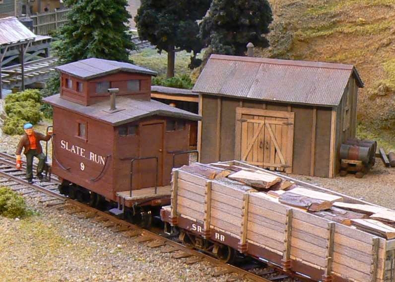
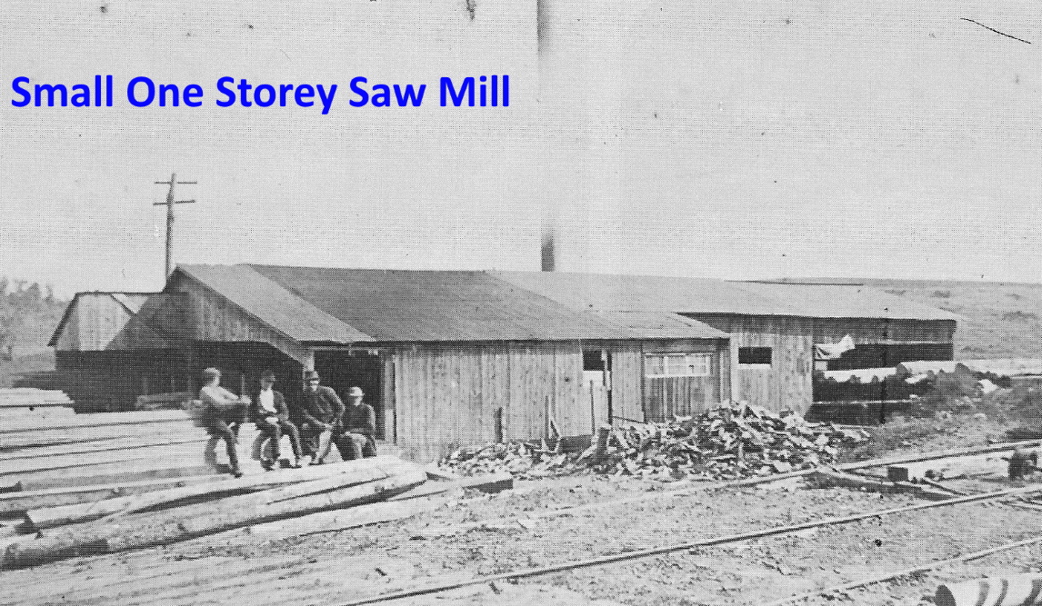
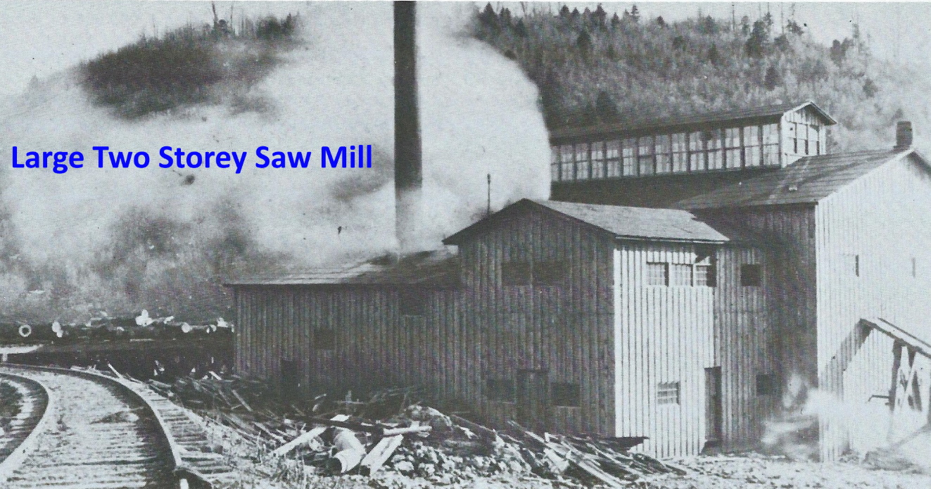
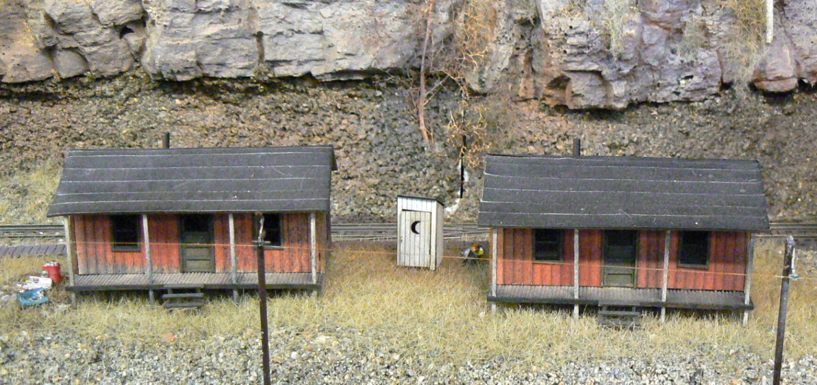
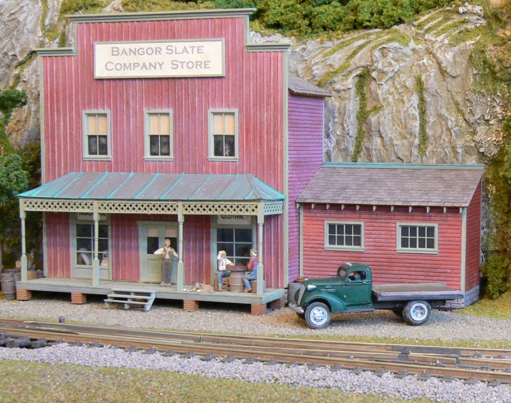
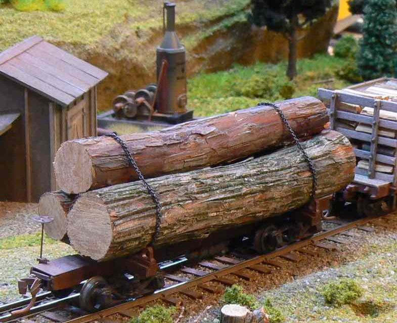
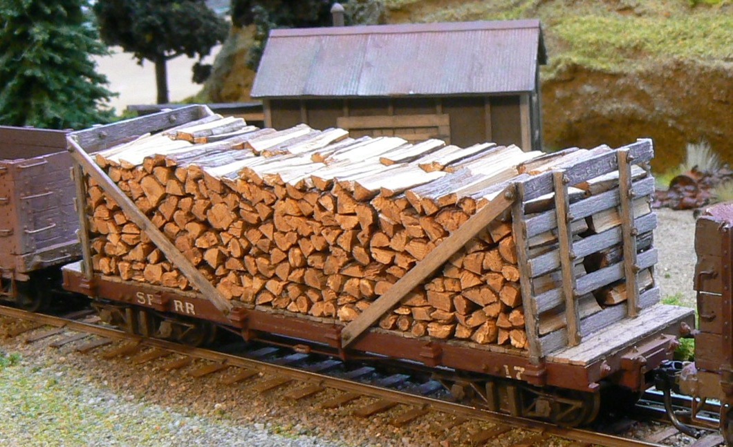
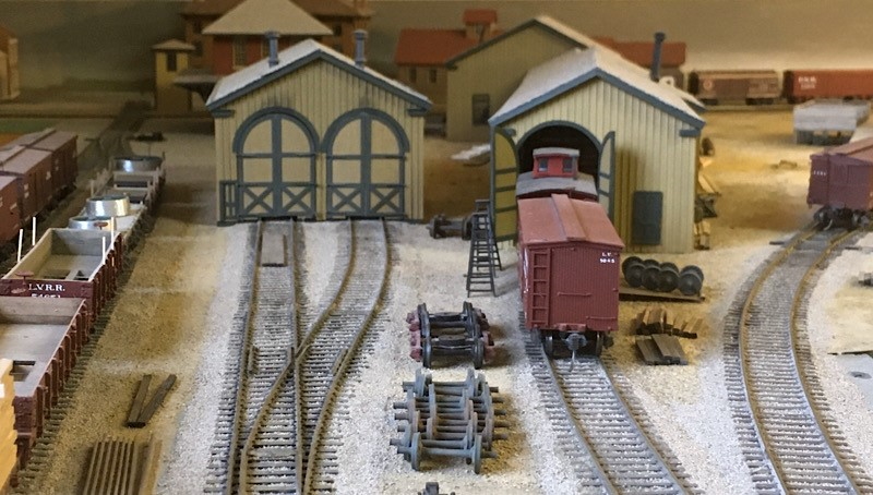
Structures bring model railroads to life. Railroad buildings such as passenger stations, freight stations, engine houses, and section houses provide places for the railroad service and maintenance employees to work. Factories and businesses provide customers. Mines, farms, quarries, and wells yield raw materials that railroads ship. Houses, hotels and mobile homes protect our little people from the elements. Bridges, tunnels, and culverts are necessary parts of rail infrastructure. Fuel facilities keep the trains running. 
 

Selecting Structures for the Layout

Placing a few structures on the layout is probably the first thing the model railroader does once track is laid and trains are running. But a more permanent selection takes some thought and raises a few questions for the beginner. Selecting specific buildings depends on a combination of factors: what is available on the market; what is appropriate for the time and place of the layout; the space available; the ability of the builder to construct kits, modify kits (kitbashing), and build from scratch; and the modeler's vision of what he or she is trying to accomplish.
 

San Antonio depot on the Southern Pacific Railroad.
 
Having a rough idea of the period and of what types of structures would be appropriate for that period is helpful. Structures help define the time and place of a layout. As a good place to start, decide on the architecture and colors you want to adopt for your railroad; a model railroad based on a particular prototype can have a consistent look if the motive power rolls up to a depot with the look and paint colors used by that railroad. Railroads across the country established an identity in part through architecture, for instance, stucco buildings in the southwest. Many railroads had standard plans for stations and other buildings.
 
Consistency of architecture with the era being modeled takes a little sensitivity to changing architectural styles through time. A layout set in the early twentieth century can include any building constructed before that time. It should not have suburban ranch houses, to pick an obvious example. Locales set well into the diesel era should probably not have a water tank for steam locomotives but could have a foundation for a torn-down tank. Another example is the large concrete coaling towers for steam locomotives that lasted long past the steam era because of the sheer cost of tearing them down, so setting one on the layout gives a sense of history. Similarly, suburban tract houses all seem to look the same across the nation, whereas historic structures tend to be very regional and appropriate models on a layout can establish the desired region. While thinking of structures and architecture for the layout, consider which vehicles and figures are appropriate for the era being modeled. Vehicles can quickly identify a period. For example, horse-drawn wagons alone on the layout date the period to before the 1900's.
 

Ready-Built Models

Several manufacturers now make model structures that can be taken out of the box and placed directly on the layout. The significant savings in time is offset by the higher cost and limited range of structures available. These pre-built models are fully painted, perhaps with weathering to give them a realistic look. They often have details such as figures, vehicles, appropriate junk and lights. With a little work adding suitable ground covers, they have the potential to create an almost instantaneous mini-scene.
 
Train shows and the Internet provide a source of ready-made structures built from kits as modelers change focus in their modeling, want to dispose of surplus models, or executors of estates recognize the value in model railroad equipment. Unlike commercial pre-built structures, products assembled by others from kits vary in the quality of construction, finishes, and detailing. Therefore, train shows allow one to see the model first-hand and determine whether size and appearance meet expectations. In addition, there are skilled craftsmen who build models as a business.
 

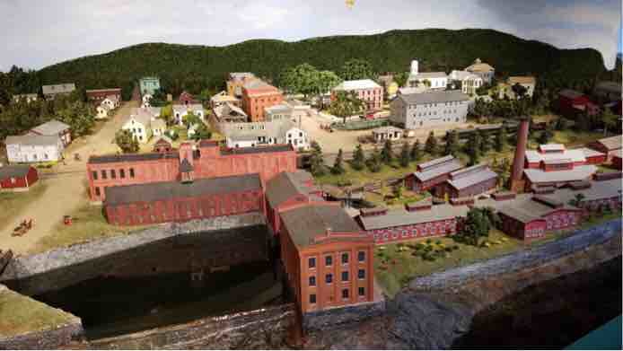
City scene built with a mix of kits and modified kits.
 

Kits

The wide variety of structures available, at relatively low cost and meeting a range of modeling skills, accounts for kits representing the majority of structures on model railroads. Kits are available in various materials such as styrene, wood, resin, plaster, and card or paper. Most beginners will probably start with styrene kits due to their simplicity and availability. This section will mostly cover basic information on styrene and wood kits.
 

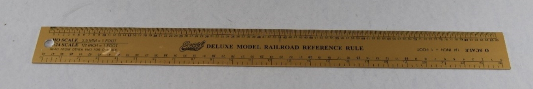
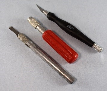
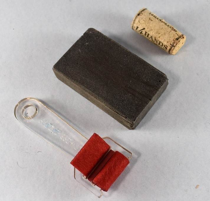
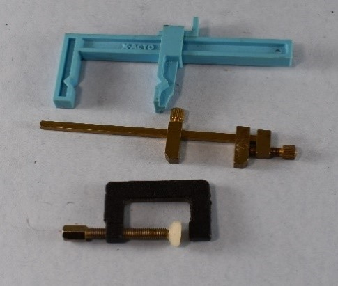
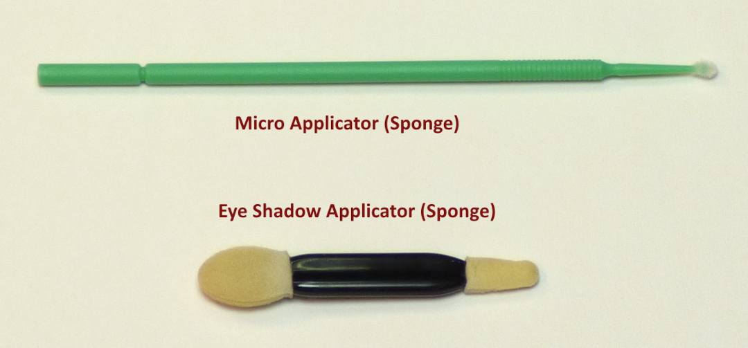
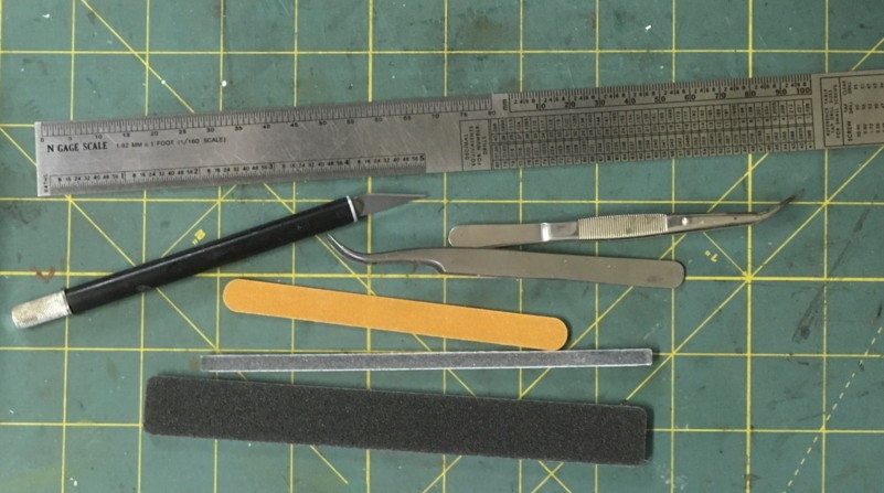
Cutting mat with basic tools for building kits: from the top a rule with multiple scales, an X-Acto knife, tweezers, cosmetic emery stick, and sanding sticks.
 
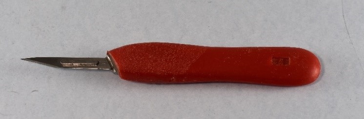
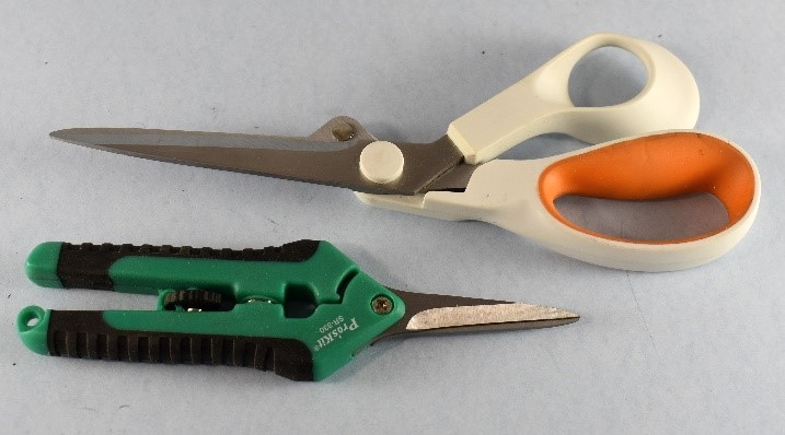
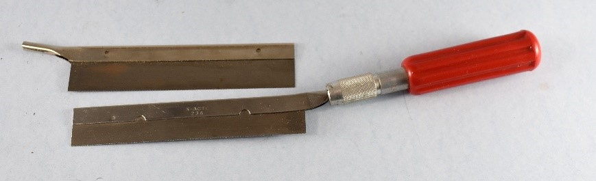
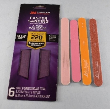
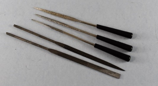
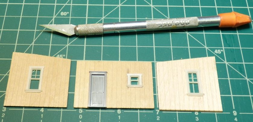
Basic tools and materials for building kits include sharp knives such as X-Acto(r) knives, scalpels or razor blades; emery boards, files, sandpaper or sanding sticks to clean up edges and metal castings; a scale rule to use as a straight edge; tweezers to pick up small or delicate parts; glues or cements; and paints. (A more complete coverage of tools for modelers can be found in Part 11 of this Guide.) For plastic kits a sprue cutter is useful to separate parts from sprues. To protect the surface of your table, you should get a piece of mat board or a cutting mat from an arts and crafts supplies store.
 

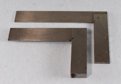
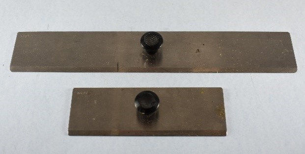
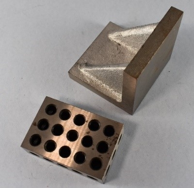
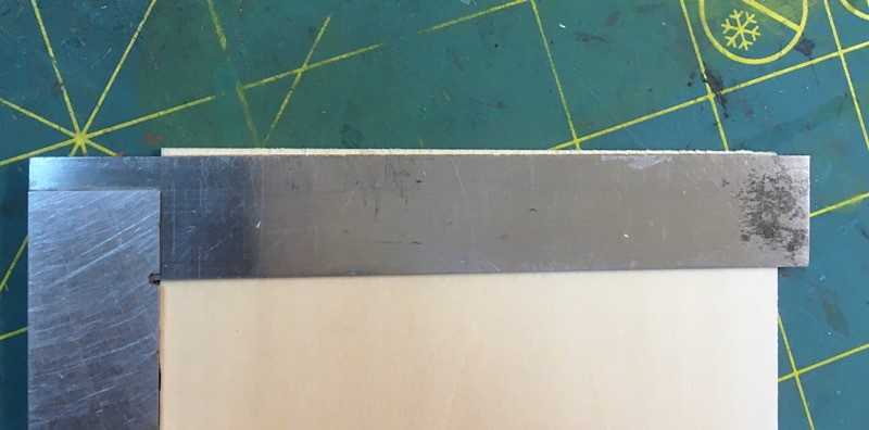
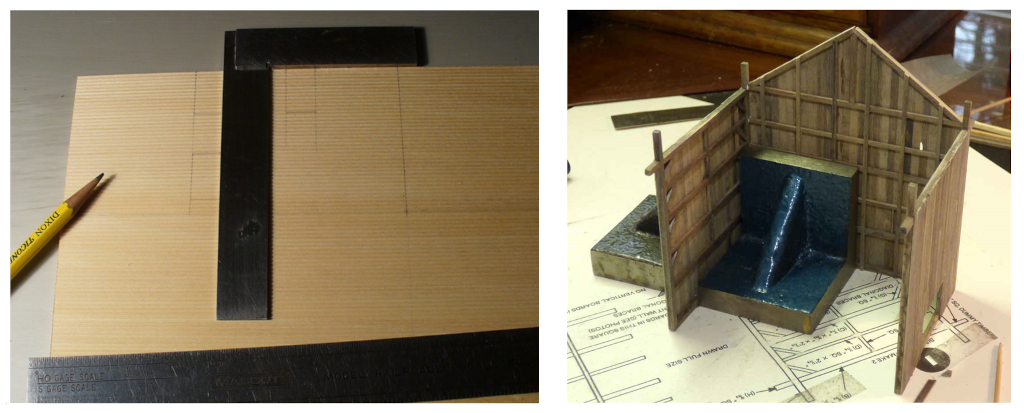
Hobby square and an angle plate.
 
A small hobby square is invaluable for laying out and cutting walls and openings and for keeping your corners square when gluing walls together.
 
Angle plates help to ensure walls are glued at right angles and perpendicular to a surface.
 
Looking at styrene kits, some are as simple as four walls and a roof, perhaps with a chimney. All details such as windows and doors are cast into the walls. The builder might need to clean up the edges a little before joining the walls. Care should be taken to keep the corners square when gluing them together. If the model has a base, it will hold the walls square but otherwise angle plates or a combination of your square and metal weights with right-angle corners can do the job. As with any plastic kit, liquid cement must be kept off visible surfaces. Although less of a concern if the building is to be painted after construction, styrene solvents may mar the surface of raw plastic. The easiest way to glue parts together is to join them and apply styrene cement along the joint with a fine brush, letting it wick between the surfaces, essentially welding the parts together. So, add a couple of fine brushes to your toolkit.
 
Styrene kits today usually come with separate sprues for walls, doors, windows, and other details, molded in realistic colors. Assembled straight out of the box the structures look attractive and somewhat realistic --for new construction. To increase realism, some weathering could be added as described in Part 10 of this guide, especially if the structure is to represent a railroad building, a customer served by the railroad, or dwellings and businesses in the grittier part of the city. Even for new buildings, adding a coat of Testors™ Dullcoat or some weathering will cut the unrealistic shine of new plastic.
 
It might seem unnecessary when a kit has perfectly acceptable colors, but painting some or all of the structure has several advantages. It will cut that new plastic look of unpainted styrene. Second, you might want to use colors typical for your geographic area or era being modeled. For instance, Victorian and early Twentieth Century houses often had a body color plus one or more trim colors, whereas mid-century suburban houses might be painted all one color. Railroads had standard colors they used on their depots, freight houses, and maintenance buildings. Finally, paint customizes your structure so that it looks unique to your railroad.
 
When using more than one color, painting parts before construction guarantees good color separation. You can build the walls before painting because they will generally be all the same color, but windows, doors and other details can be painted on the sprue. For best results in cementing parts together, either avoid getting paint on the surfaces to be glued or remove paint on these surfaces before joining the parts. You always want good plastic-to-plastic contact for the cement to actually soften and join the parts.
 
Wood kits range from the very simple to the very complex craftsman kits. Traditional wood kits come as sheets and strips of wood and other materials, as well as castings. The sheet-wood has been milled to look like clapboard siding, board and batten, or planks. Windows and other details are often metal or styrene castings. With some important exceptions, the contents of this type of kit are appear similar to what you would have if you were scratchbuilding. Sometimes the sheetwood parts are already cut to size, perhaps with door and window openings cut out. More importantly, the kit comes with instructions, including detailed step-by-step descriptions of the recommended construction sequence, measurements, plans, diagrams, and templates as appropriate. The builder is saved the time and effort of finding or drawing plans, collecting the raw materials, and figuring out the best a work flow to build the kit, hoping it turns out. The person wanting to learn scratchbuilding might want to start by constructing one of these kits to build gain experience in working with raw materials.
 
Here are some helpful YouTube links on building wooden kits:
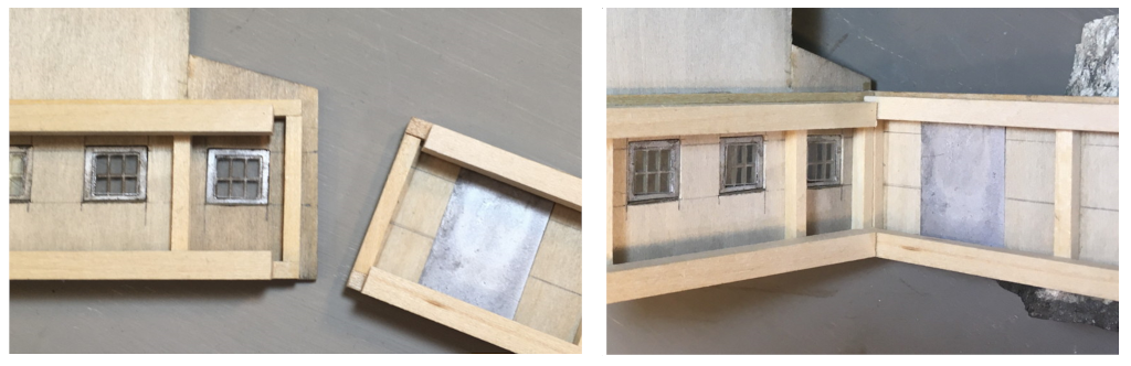
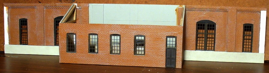
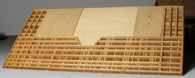
Today's laser-cut kits follow a different approach. The kit typically comes as a set of laser-cut sheets that make up the walls, trim, windows and doors, as well as detail parts of various materials. Structures comprise a sturdy core made up of walls that interlock. Larger structures require bracing on the inside of the core. A modicum of care yields a sturdy substructure with square corners and walls that line up precisely. To this core the builder applies layers of siding and trim made of card, wood or thin styrene. All these components have been cut accurately so that the task of the modeler is to line everything up when applying and gluing the layers. Because walls and windows are built up in layers, the modeler can easily paint the structure in multiple colors, such as in this example of a B&O telegraph office.
 

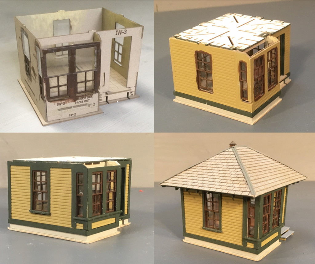
Stages in building a laser kit of a Baltimore & Ohio telegraph office, from the basic core (upper left), addition of wall sheathing (upper right), trim (lower left) to completion (lower right).
 

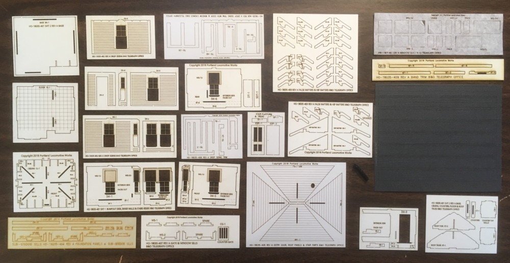
Contents of the kit for building the B&O office shown above.
 
Wall and trim sections usually come still attached to the surrounding material and the builder must cut them out by slicing through little connectors with a sharp knife. Once cut out, the remaining little pieces of the connectors should be cut or sanded off. Similarly, after the core is assembled, the corners should be checked to see if any of the interlocking tabs stick out and that the structure is square. even the slightest bit. These need to be filed or sanded a little until the wall is perfectly flat and ready to accept the layers of siding and trim.
 
A wide variety of buildings are available in laser-cut kits, including simulated wood, brick, and cinder block structures. Many are railroad-specific.
 
Yellow or white carpenter's wood glue is appropriate for both traditional wood and laser-cut kits; the yellow glue “grabs” the surface and sets up more quickly than the white glue. Gluing dissimilar materials, such as plastic or metal to wood or card, is best accomplished with a cyanoacrylate or "superglue" (CA). The gels set more slowly than the ordinary, runny CA. Do not apply glue directly; put a little puddle on a scrap piece of plastic and use a toothpick or wire to transfer glue to the parts.
 
"Craftsman kits" are considered to be advanced, requiring a lot of cutting and fitting. Many are large kits that include complex buildings or multiple structures, many details, and extensive directions. The more complex kits may include components in resin or plaster in addition to wood, and often can be built up into small dioramas. Building these kits has become almost a hobby within model railroading. In almost every case, today's craftsman kit includes detailed instructions laying out the construction sequence, templates, and methods for staining, painting, and weathering. Due to their complexity, these instructions may actually come as a book, which may be a useful source of techniques for the modeler in future projects.
 
Finishing: Paint and Stain
Acrylic paints can be used on all structures. Whereas best results are achieved with an airbrush, acrylics flatten well after application so brushing can work remarkably well. Similarly, spray cans work well with but require some care not to apply too much paint at a time. As a general rule, for any type of painting method, multiple thin coats work much better than trying to cover in one thick coat. Non-acrylic paints can also be used if one is careful to check that they are compatible for the plastic being used.
 
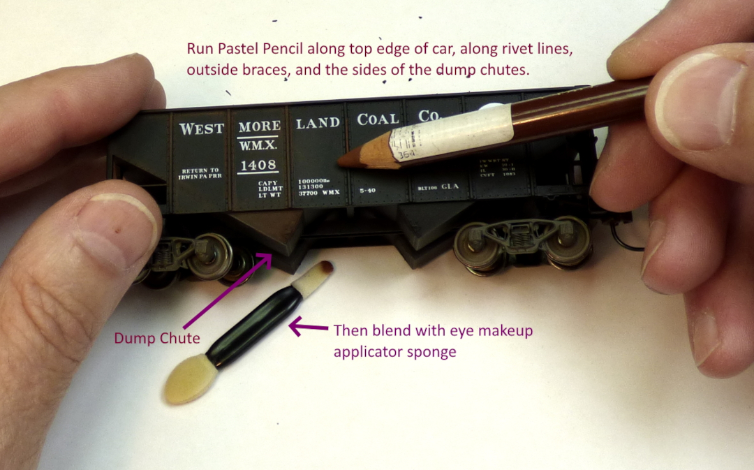
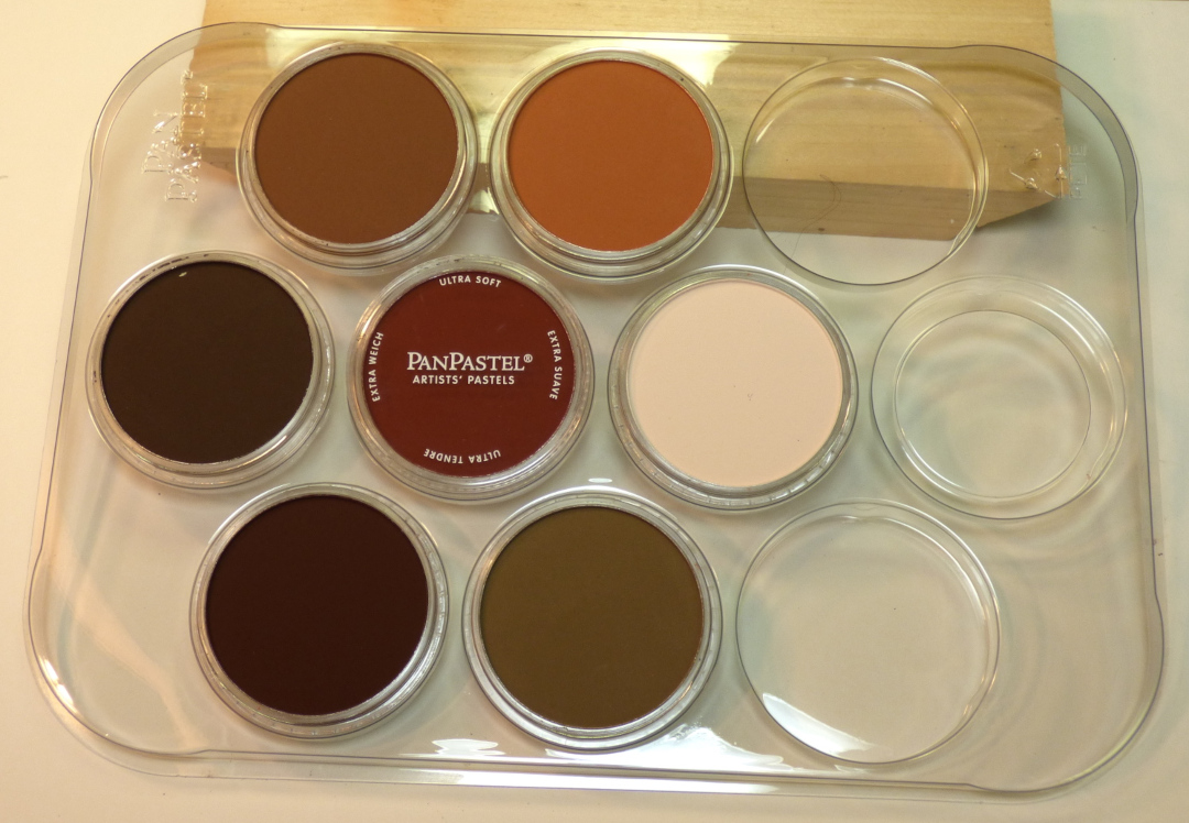
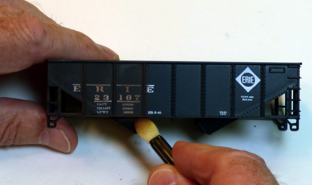
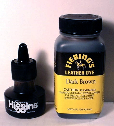
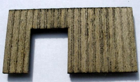
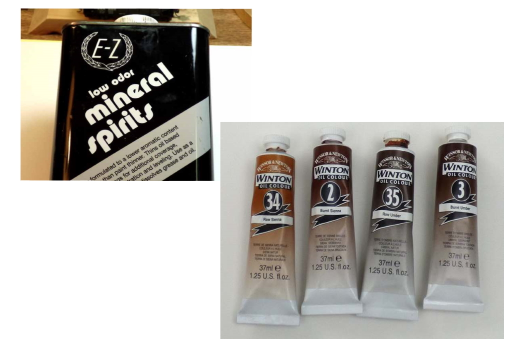
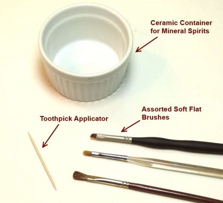
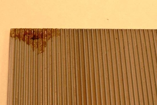
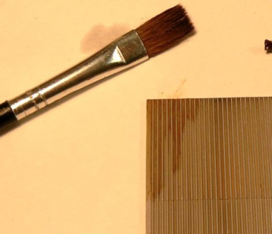
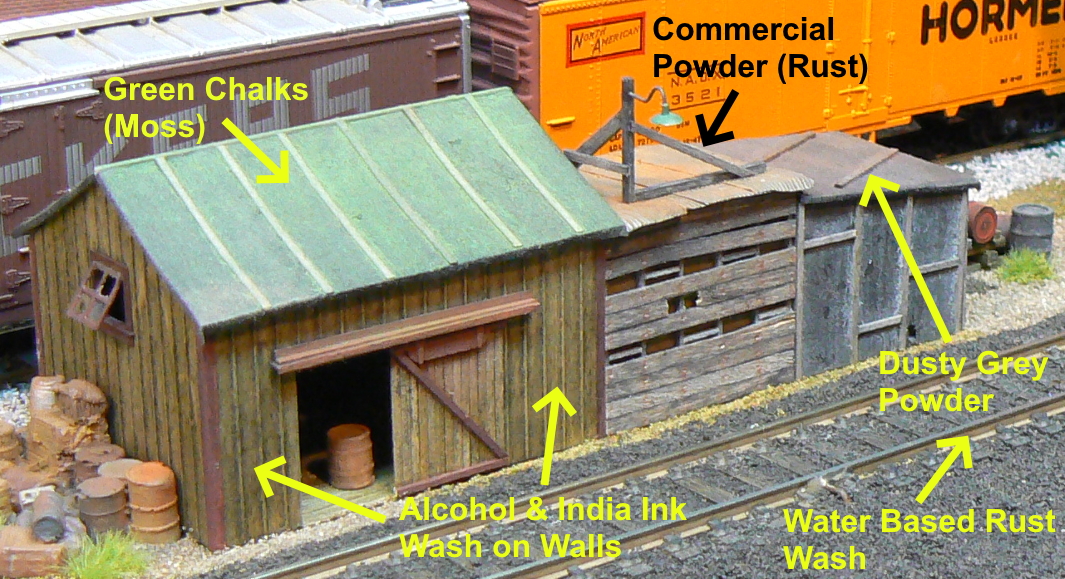
Rather than paint, you can stain wood parts with weathering mixtures available from a number of companies. The builder should take care to keep glue off visible surfaces, because dried glue effectively seals the surface and resists stains. A home-made mixture of India ink and alcohol can be used as described in the weathering chapter of this guide. Even styrene can be made to look like weathered wood by spraying a base layer of a tan to khaki color and staining with an india-ink-alcohol mixture.
 

Scratchbuilding

Building from scratch allows the modeler to build models not available in kit form, perhaps at a substantial savings in cost and with the benefit of uniqueness. Building a model from scratch requires a plan; a few tools in addition to ones listed above; raw materials including sheathing for walls and possibly castings for details; and basic construction skills.
 
Plans can be as simple as a sketch with a few critical dimensions. The beginner should probably start with a scale drawing. Good sources for plans are commercial magazines, the NMRA Magazine, and railroad historical societies, either on the Internet or in print. Sometimes a plan of the desired structure can be found can be located similar to the structure desired, requiring just a few adjustments to overall dimensions and style and dimensions of doors and windows.
 
Photographs can also provide a starting point, especially if a building is extant and all sides can be photographed straight on. If it is impractical to measure the building, you can include a person or a yardstick in the photo for a scale.
 
Maps such as Sandborn insurance maps provide building footprints for basic dimensions. Some graphics software can correct for perspective. Counting boards of a known dimension on a frame structure or bricks gives vertical dimensions for walls, windows and doors.
 
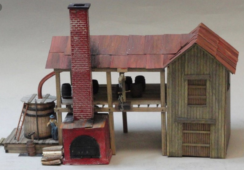
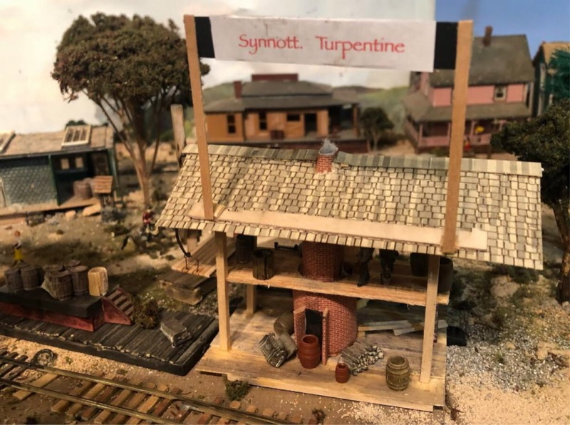
Sometimes plans come from inspiration, resulting in freelance models. Inspiration can come from an actual structure, a kit model that is no longer available, or another person's model. For instance, the Synnott Turpentine structure shown below was built from several photos of a model. Because the modeler took a few liberties and used some imagination, there are many differences between the influencing photos: and the final product:
 

The inspiration for a model still.
 

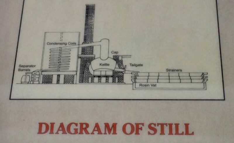
A basic plan for a prototype still.
 

The finished model of a turpentine plant.
 

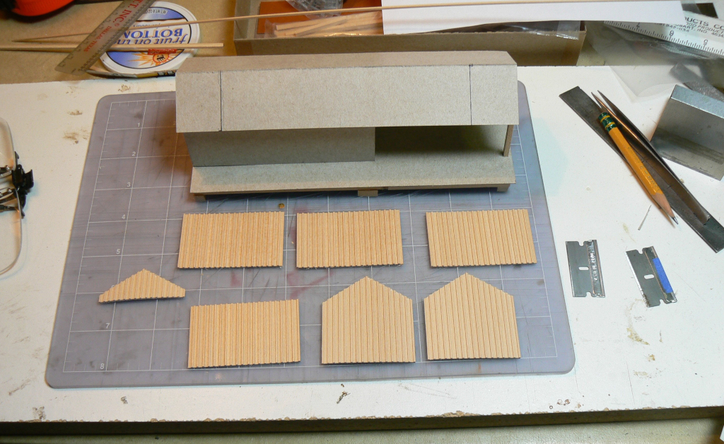
Example of a cardboard mockup and the start for the actual model.
 
Mockups are provisional, quickly-built models that can help one visualize how a projected structure will look on the layout. Questions can be answered such as:, whether it fits the space, looks appropriate, and seems large enough without unduly dominating a scene. Mockups are particularly appropriate when the structure will be inserted into an already existing scene or the builder wants to try different locations and maybe even different configurations of substructures.
 
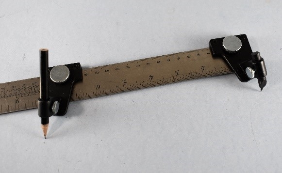
Tools on the scratchbuilder's workbench should include a scale rule or dividers to transfer dimensions from drawings to working materials. A rule with multiple scales is also extremely useful if you build a model in a scale different from the plans.
 

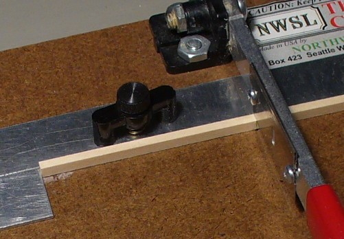
A chopper being used to cut stripwood.
 
A chopper speeds up cutting multiple pieces of stripwood or styrene strip to the same length.  A small fine-tooth saw helps in cutting thicker pieces of stripwood.
 
There might be occasion to need drill bits and pin vise. Some modelers cut out a window opening by first drilling small holes near each corner, cutting between the holes, and cleaning up as necessary with a file, emery board or sanding stick.
 
Building materials such as plain sheets of wood and dimensional lumber can be found at popular art stores. Well-stocked hobby shops stock sheets of wood and styrene milled to represent clapboard, board and batten, and plain boards, as well as dimensional (or fractional) lumber (1/8" by 1/8", etc.) and scale lumber (scale 2" by 4"). Other sources are include online retailers and the manufacturers themselves. Most manufacturers of model railroad scratchbuilding supplies will sell directly to individuals.

Walls cut from sheetwood with castings used for windows and door.
 
Details such as castings for windows, doors, chimneys, and architectural features are difficult to find at most hobby stores but may can be ordered from manufacturers.
 
Building from scratch uses many of the same steps and skills as constructing a kit from sheet materials and castings. That is why for some people building a few kits may provides a step up on the learning curve to full scratchbuilding. Similarly, model railroad magazines run articles on scratchbuilding for beginners with step-by-step instructions, much like those supplied with in a kit.
 

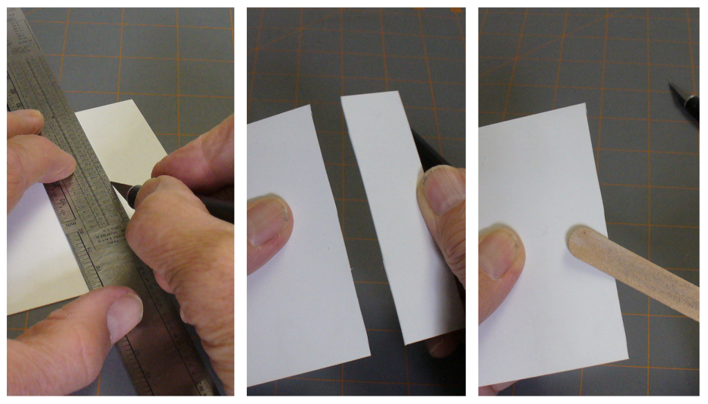
Squaring up sheetwood.
 
The builder can form several habits useful for both kitbuilding and scratchbuilding that lead to clean, square, and accurate construction. The most important cuts in laying out a wall are the first two you make. Do not assume sheetwood is milled with simulated boards exactly parallel to the long dimension or that the end is true. Edges are often a little rough so it's a good practice in any case to cut a new edge lengthwise exactly parallel with the simulated boards and to cut a new end using the square and the new, clean edge. This might not be necessary, but check with your eye and your square. Styrene sheet milled to look like clapboard or board and batten is usually accurate.
 
Change knife blades often; even soft woods and especially styrene wear blades out quickly. A dull blade causes the knife to wander and follow the grain, or when cutting stripwood, compresses the wood before it cuts and yields an edge that is not clean.
 
Use multiple light passes of the knife to cut through sheet material and never force the blade through the material. This is true for both wood and styrene.
 

Cutting styrene sheet by first scribing (left), snapping (middle) and cleaning up (right.)
 
Scribe and Snap styrene. In other words, scribe several times and then bend across the scribed line to snap the pieces apart. Scribing styrene tends to raise a small ridge so go back and clean up the edge with fine sandpaper or sanding stick if the edge is going to show in the model.
 
Be neat when using glues and cements. Use only as much as necessary. Excess glue can slow down drying time and can squeeze out, remaining unnoticed until dry, and detracting from the appearance of the model, especially if the material has not been pre-painted or stained. Check your work and remove visible glue before it dries.
 

Well-braced walls with the sturdy bracing being used as glue surfaces when the walls are joined together.
 
Brace structures well, especially for the larger scales. By planning ahead, a person can use vertical bracing at or near corner edges to provide glue surfaces. Bracing around the perimeter can support floors. Even if the interior is not to be detailed, floors block light from going through the whole building and can guarantee the building is square.
 

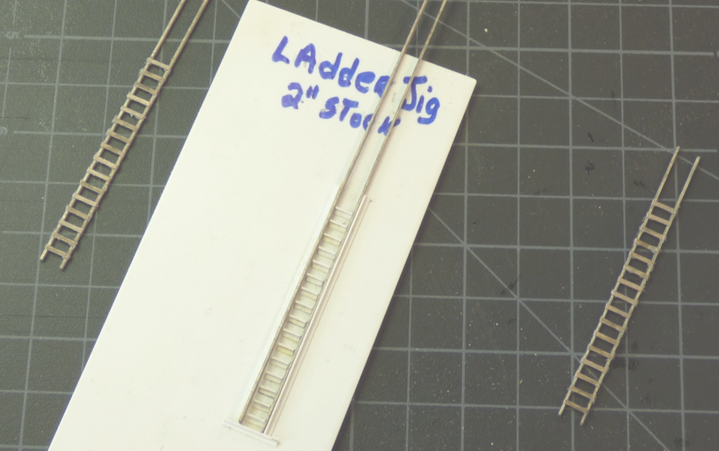
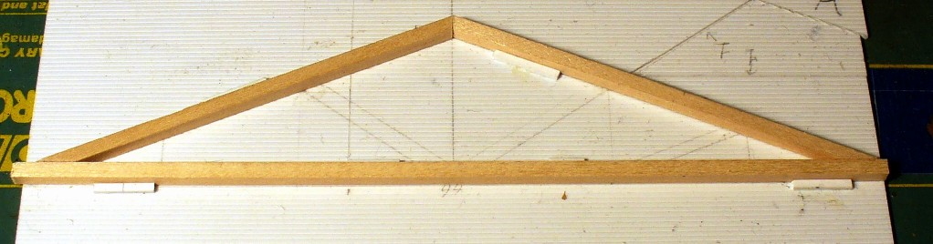
Jig for making rafters.
 
Use jigs to cut out or join components of details when multiples are required, for example the decorative trim under depot overhangs and rafters.


Jigs for such things as wooden ladders (shown above) can be used over and over.
 

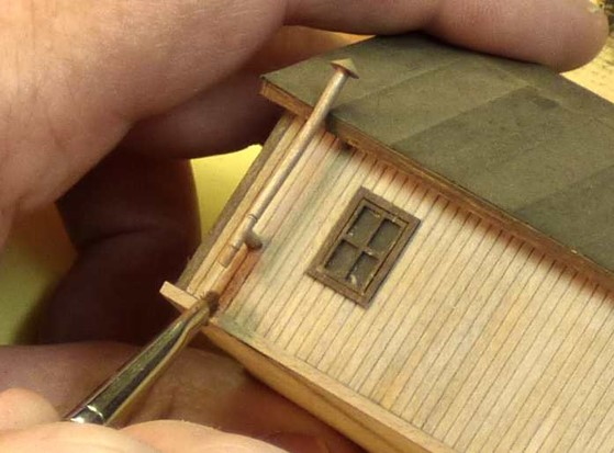
Adding trim by gluing a long piece of stripwood (left) and cutting the excess (middle), results in a clean, accurate product (right).
 
Don't try to measure each piece when adding trim to buildings. Cut each piece a little long, glue in place, and cut off the excess. Look at the results and, if still a little long, file off and clean up with a fine file or sanding stick.
 
Paint major components before assembly to get good color separation. Even if trim and body are to be the same color, painting before assembly avoids those little thick areas of paint that occur around joints and corners.
 
Brick structures take special consideration. Although modelers can buy laser-cut wood in a brick pattern, the usual method requires covering a styrene substructure with simulated-brick sheet using a water-based contact cement. Alternatively, a solvent-based styrene glue can be used but only around edges of the walls and openings. Trapped solvent can eventually distort the outer skin of styrene.
 

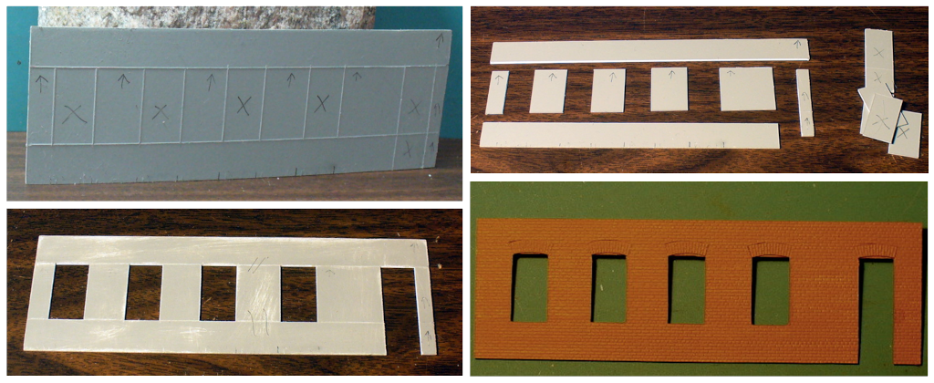
Constructing a masonry wall with styrene sheet for a subwall and a thin styrene overlay with a brick pattern. Scribe lines for windows and doors in subwall (top left), snap pieces apart (top right), glue wall pieces back together (lower left), and glue brick overlay on subwall and cut out window and door openings (lower right). 


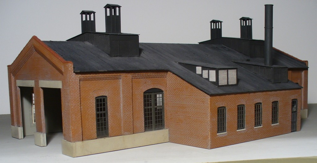
Partially completed (top) and finished model of B&O shop in Rowlesburg, WV (bottom).
 

Because the brick overlay will hide the subwall, windows can be cut out by scribing horizontal lines at the top and bottom of a complete row of windows, scribing vertical lines for the window sides, and snapping all the pieces apart, keeping track of which bits to keep and which to discard. Walls are reassembled from all these pieces leaving out the pieces where openings will go. The brick sheet is now cemented to the subwall and openings cut out carefully from the back. Windows and doors in brick buildings rarely have trim, but instead are recessed. Castings for double-hung windows are glued on the back, backwards and upside down so that the sashes have the correct alignment.
 
Styrene can be braced with heavy styrene strip or with wood. Adding floors helps to brace construction and make corners square if fitted precisely. Wood bracing provides a lot of stiffness. A contact cement like Pliobond or Walthers Goo can join styrene and wood. Because these are solvent cements, apply a little evenly along the length of wood; press it in place but remove it immediately, leaving some of the cement on the styrene; let everything sit a couple of minutes until most of the solvent evaporates; and rejoin the pieces. The contact cement really grabs the materials and the wood brace is now permanent.
 
Brick details can be built in a couple of ways. The furnace in the turpentine factory was made from two wood dowels that were cut to size; and a paper simulated brick sheet was carefully glued on.
 

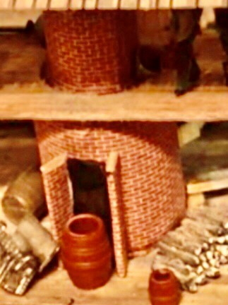
Furnace made from wood dowels with simulated brick paper overlay.
 
If the brick sheet is thick enough, chimney sides can be cut out, edges beveled, and the pieces glued together.
 
Board on Board Construction
The beginner might have heard of "board-on-board” construction and wondered what it means. Usually looked upon as an advanced approach to scratchbuilding, board on board construction is the use of scale lumber in a prototypical way by building a frame to which individual boards are added. Building large structures this way admittedly requires a lot of precision craftsmanship and can become tedious for the impatient, but it is nevertheless a useful skill to learn for small building components such as porches and loading docks. Board on board construction is particularly effective for unpainted structures or components because each board takes on a slightly different shade of the weathering stain, unlike the uniformity generally obtained with sheetwood.


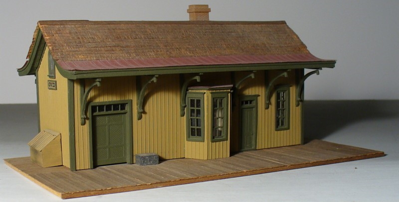
The station platform was built from individual boards for joists and deck, the depot floor from scribed sheetwood.
 

Using scale lumber also yields more delicate building components. Floorboards for a porch made from scale lumber can be a scale inch or two in thickness rather than the thickness of sheetwood, the most-readily available thicknesses of which approach 3" in O scale and more in HO and smaller scales. The results can be very satisfying even for small components. This depot platform was built by constructing the frame and gluing on pre-stained stripwood. One way to hold frame elements in place until glued is by utilizing double-sided tape on a flat surface.
 
Many a craftsman kits provides a good entree into board- on- board scratchbuilding. This approach might be used for a subset of components, or throughout the kit. Rather than using individual boards on a frame, some kits have a laser-cut wood shell on to which the builder glues individual boards. Thus, there are ways for the beginner to learn this useful approach to building models.
 

Kitbashing

Practicing the art of kitbashing ranges from rearranging sub-assemblies of a kit-built structure, cutting off the front of a building to use as a "flat" in the background, cutting up and recombining walls, to mashing together two or more kits. Kitbashing utilizes skills from kitbuilding and scratchbuilding and, the imagination to see visualize a new structure from a kit. , and In addition, the modeler must possess the knowledge of which kits are on the market that can be modified to fit a spot on the layout.
 

A kitbashed structure built to set against a backdrop.
 
Layout builders often use shallow, partial buildings set right up against the backdrop to give depth to an urban scene. Using just one wall of a kit against a backdrop is a simple kit modification, but arranging front and back walls of a factory side-by-side to create one long structure and adding downspouts or chutes or other features to hide the seam is a first step to kitbashing. Imagine now gable ends arranged in-line with these wall sections, perhaps with small cut-off sections of walls adjacent to the ends to provide a more 3-D model. Windows could be bricked in, window openings enlarged to accommodate doors.
 
Kitbashed structures can spring completely from the imagination and can be complex, with many added details and weathering. Urban landscapes call out for such creativity to give the impression of Gotham in a limited space. Kitbashing comes in handy to approximate an actual structure by modifying a kit on the market.
 
Kitbashing does not ordinarily require special tools. Modifying wood structures is akin to building a craftsman kit or scratchbuilding, but the modeler might want to use heavier knives or even hobby saws to cut up styrene walls. To make sure a planned kitbash will actually work and to visualize the results, you can use a copy machine to make paper copies to be cut up, glued to cardstock, and assembled into a mockup that can be placed on the layout. The temporary structure serves as a stand-in until the kitbash is complete.
 

Realism

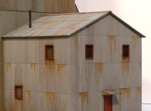
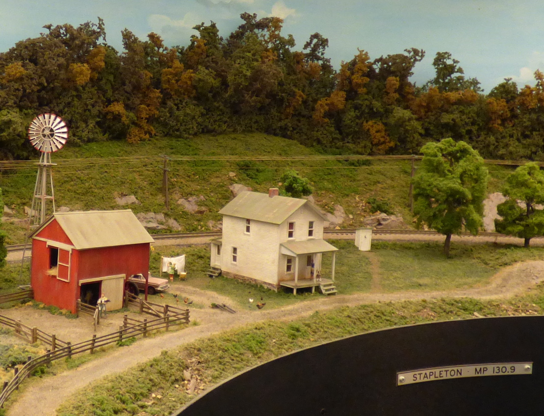
To look realistic, structures should not simply set on the layout. Work the scenery around the base of the structure, such items as grass, dirt, shrubs, trees, roads, and if it's a bridge one needs to add, ballast and the correct abutments. Always disguise the joints between the base of the structure and the ground surface. If the a building does not have a proper basement, consider building one right on your layout that extends down into the scenery; the slight overhang of the structure walls should disguise the joint. Use weathering to cut the shine of newness, and give a house that lived-in look or a factory that worked-in look. Above all, put each structure in a setting that makes sense and with the details and scenery that would logically surround a structure.
 
These things should be kept in mind if you are going for the Golden Spike Award.  NMRA requirements include the following for structures:
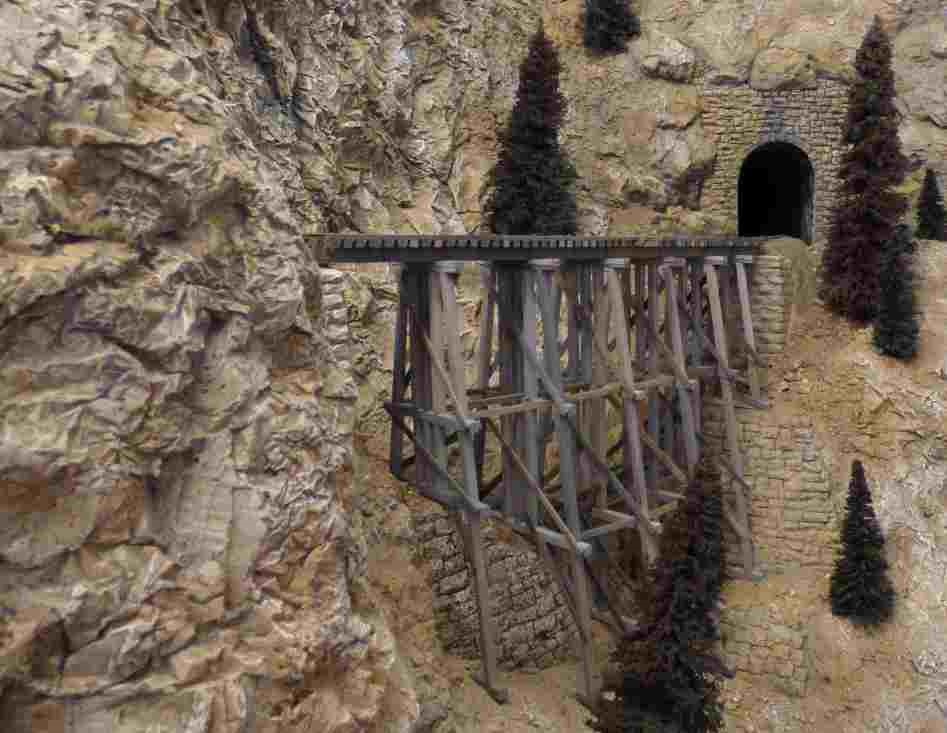
Construct five (5) structures (scratchbuilt, craftsman, or detailed and commercial kits). These structures may be separate, or one or more of them may be part of a single scene. The same comments apply here about the type of kits. The idea is to show that you can do more than glue a simple plastic kit together. Painting or weathering are good things to consider. Remember that "structures" aren't just buildings. Things like bridges and trestles also fall into this category.
 
Building a few detailed structures from kits or scratch with reasonable neatness and precision, painting them in realistic colors, doing a little appropriate weathering, and working them into your layout in a realistic way should garner you a Golden Spike Award, plus make your model railroad look like an actual, living place.
 

Additional Resources

Internet searches can yield many how-to write-ups, online discussions, and videos on building kits and scratchbuilding.
 
Vendors
The NMRA has a Partnership Program with many vendors that allow NMRA members receive discounts for a wide variety of items such as kits, scratchbuilding supplies, ready-to-run models, etc. More information on this program is available at https://www.nmra.org/partnerships.

Beginners Guide Part 6: Scenery

Not long after you have decided your scale, track plan, built your bench work and started running a train over the new layout you will start to imagine that there is something beyond the track, a small part of the world to be filled in with hills, valleys, buildings, and all the other things we see around us.  We call this scenery.  It comprises the basic landform, its color and texture, rocks, grass, bushes, streams, trees and all the other aspects of nature you want for your miniature world.  It also includes manmade structures such as houses, stores, factories, roads and so on, but we'll cover those in another section.
 
Unlike laying track or wiring which are crafts, scenery, which does involve technique, is largely an artistic endeavor.  You may be copying a photo or reproducing a picture you have in your mind.  In both cases you are creating a three-dimensional representation, and it has to feel and look right to you.  Take another look the next day.  Is it what you have in your mind or does it need some tweaking?  That's art.
 
As you learn the techniques and the materials you will get better and better.  Don't be afraid to experiment on and off the layout.  There is nothing in scenery that can't be repaired or done over.


Creating Landform

While many methods have been used over the years two currently stand out: 1.) carved layers of structural Styrofoam board and 2.) plaster-impregnated gauze molded over a lattice of cardboard strips or wadded-up paper.  Styrofoam sheets can be found in the big box home improvement stores in 4'x 8'sheets in 1"and 2"thickness.  The pink (Owens-Corning) or blue (Dow) are best.  Avoid using white foam which crumbles into beads.  Plaster gauze is generally available at hobby shops in 12" wide rolls.
 
To use Styrofoam to make hills cut it into layers representing the contours of your hill, each higher layer a little smaller than the one below.  Next glue them together using panel adhesive.  Make sure it is compatible with Styrofoam.  Another way is to use low temperature hot glue.  This goes faster and the foam is ready to carve sooner.  The next step is to use a long-bladed utility knife or a hotwire foam cutter and carve off the steps to create the slope of the hill.  Then smooth out those slopes using a Shurform file or 40 grit sandpaper.  A much faster way is to use a drill/driver with a cup style wire brush.  This takes a little getting used to but works well.  Make sure you spray the foam with water to prevent the particles from getting all over.  You can then paint over the textured surface or cover it with a filler "goop" such as Sculptamold, available at most hobby shops.  Another option is US Gypsum’s Easy Sand 90 Lightweight Setting-Type Joint Compound available in 18lb bags at Home Depot.  Adding "goop" also allows you to embed small rocks or plaster rock castings.
 

Using plaster gauze
 
To use plaster impregnated gauze, you first need to make a form to simulate the basic shape of the hill.  This can be done with wadded up newspaper held down with masking tape or corrugated cardboard strips which are stapled or hot glued down at one end and attached to a stick or a ridge board at the other end at the top of the hill.  Horizontal strips are interwoven through the vertical pieces to complete the form.  Once this is done, cut square pieces of the gauze, dip each one into a shallow pan of water for 4 -5 seconds, and drape it over the form.  Overlap successive pieces about 25% until the form is completely covered.  The plaster will take several hours to set before proceeding.
 
Large rocks and rock cliffs need to be added to the landform before adding ground cover.  You can certainly use actual rocks that look good as miniature rocks.  However, they are heavy and not easy to find in quantity.  The most prevalent way to make rock is to use plaster castings.  These can be purchased or made using latex molds, which in turn can be purchased or made.
 

Coal makes great form for rock molds
 
Latex Molds - Let's start here.  Purchase some liquid latex.  This is readily available at hobby shops or craft stores such as AC Moore or Michael's.  Find a rock that looks good in miniature.  Large chunks of coal make super masters.  You'll need a number of molds, so think about making several at the same time.  Wash the rocks with detergent and rinse off.  Stir the liquid latex and using a 1" to 1 1/2" throw-away foam brush, brush on a coat of latex covering the part of the rock you want to replicate.  Let dry for several hours, but immediately clean the foam brush in detergent and hot water.  If you're lucky a single brush will get you through all five or six coats of latex which you will continue to apply.  If any of the molds is any larger than 3" to 4" across, after five coats you may want to reinforce it with a layer of cloth embedded in the final coat.  To do this cut a piece of woven - not knitted - cotton fabric (an old bed sheet works great) slightly larger than the mold.  Apply a coat of the liquid latex then immediately push the cloth into the wet latex and apply another coat over the cloth.  Let dry, and you are done.
 

Latex rock molds
 
Plaster castings - This is the next step.  Buy a bucket of Plaster of Paris, again at a craft store.


This makes the best rocks because it can be carved and, counter intuitively, because it can be easily broken or nibbled away.  Like you did with the molds consider making several at a time.  Clean the molds with detergent and water and lay them out.  Next mix a small quantity of plaster with water.  It should be the thickness of pancake batter, essentially as thick as you can pour.  Pour a thin coat into each mold.  Using a 1/2" flat stiff bristle brush, (as used in oil painting) you can push the plaster around in each mold to make for a thin but  uniform coating.  Now you have to mix and apply the plaster very quickly because it will start to set in about five minutes, so work quickly.  Let the plaster cure for at least four hours.  When you are ready to remove the castings very carefully peel back the edges of the mold by pulling back along the back surface of the mold rather than away from the mold.  You will break some, but with care most will come out okay.
 
Applying Castings to the Landform - First fit the casting to the surface.  If you need to remove a little material from the edge do so by crushing the offending edge with pliers.  Don't grab the edge with the pliers and try to break it off by bending from the other side of the casting.  It will break somewhere else and ruin the casting.  You can also file off the high spot using a cobbler's rasp or other coarse file.  Difficult to explain; easy to do.
 
Next mix up a small amount of your favorite "goop" as previously described and apply a ring around the edge of the casting then gently press into the landform.  Using a 1/2"wide bristle brush push the "goop" around to blend the casting into the landform and stipple it to replicate the ground texture.
 

Tools & materials to make US Gypsum Sheetrock brand Goop
 
Making Rock Cliffs - These are done in a similar manner.  The big difference is fitting multiple rock castings together, so they look like a continuous rock structure.  This is like putting a jigsaw puzzle together where you first have to trim the pieces to fit together.  First try to make a best fit of several castings.  When you have two fitting together well using toothpicks or long steel pins pressed into the landform to hold each casting in place.  Toothpicks work well with Styrofoam board while pins may be needed with plaster cloth scenery.  Continue fitting and nibbling more castings until you reach the overall size you want.
 

Fitting & securing rock castings together to form rock cliff
 
For the final installation remove one of the castings, apply your "goop” then press the casting back into place.  Then move on to the next one and so on.  Stipple the "goop" as it starts to firm up, to blend and let dry.
 
Painting Your Rocks - While there are a number of techniques, two stand out.  One uses acrylic washes followed by dry brushing; the second employs a stippling technique using full strength acrylics.  For the wash method mix up your rock colors using acrylics cut about 50% with water.  You can use several different colors if you want.  Brush or spray these on your rocks.  Follow immediately by brushing a black wash on the side shaded from the sun.  Let dry, then using a very light shade of the base colors get a brushful and wipe off almost all of the paint until there is just a slight fog when you drag the brush across a paper, no streaks or blobs.  Then brush across the sunlit areas of the rock which will lighten slightly bring out the sun, and you're done.
 

Matching stipple painted rocks cliffs
 

Backdrop with prototype rocks
 
To do the stippling technique mix three shades of your rock color using acrylic paints: light, medium and dark.  After determining the light and dark sides of the rock, paint the dark side, with the dark shade.  Dip the tip of the brush in the dark paint then stab at a piece of scrap paper a few times until the bristles deposit tiny specks of paint (a stipple) without any blobs, then lightly stab at the rock (stipple) around to the light side with the fewest amount on the light side.  Next go to the medium shade. Stipple the dark side just a little, then more in the mid-range and light sides.  Finally using the light color paint stipple the mid area a little and the light side a lot.  This yields the right shading and actually adds visual detail.
 

Latex & white & black acrylic paints, glue and brushes
 

Painting Landforms and Adding Dirt, Grass, Shrubs, and Trees

You need to decide what is the underlying color and texture you want.  Looking at photos of terrain in the part of the country you are modeling is helpful.  Use Google images.  Is it completely covered with grass and weeds or are there areas of bare dirt?  If the former, you may choose a green color.  If dirt, a brownish paint is in order. Use flat latex wall paint for the landform in general.  For small layouts a sample size jar may be enough.  You may also want to buy bottles of acrylic craft paint colors to vary the base ground color, including both black and white to darken or lighten as required.  A small plastic paint pallet to mix small batches is in order as well.  (Get one with a cover, so your paints will last longer before drying out.)  All of this is available in the craft stores.


Vegetation and Dirt - For the former, ground foam seems to be the universal choice.  This comes in a wide spectrum of colors and sizes and is offered by Woodland Scenics, Scenic Express, Heki, Noch as well as a host of others.
 
Actual dirt can also be purchased from Arizona Rock & Mineral Co. or the other scenery companies listed above.  Another approach is simple: go outside and look at the soil around your home area.  The sandy varieties are better than clay dirt.  If you find some you like, scoop it up into Zip Lock freezer bags.  When you get back home spread it out in a baking pan and bake it for an hour or so.  Best do this Multi-color ground foams using a disposable pan on your barbecue grill.  The baking dries the dirt and kills any bugs or germs.  Sifting the dirt gets rid of extraneous debris.
 

Real ground-up rock from Arizona Rock and Mineral Company
 
Painting the Landform & Applying vegetation and Dirt - You can embed these right in the paint or simply cover the terrain with paint.  If not quite ready with your ground cover, adding just a coat of paint lets you see the terrain and may help your creative juices.  If you want to embed as you paint, add about 25% white glue such as Elmer's or Aleene's to the paint to give more adhesion.  This particularly helps on slopes.  Paint about a square foot of area then sprinkle the ground foam and/or dirt into the paint mixture.  You may let it dry as is or spray with wet water, (water with a teaspoon of dish detergent per quart), and with an eyedropper, add a dilute water/glue mixture, (1 part white glue to 4 parts water), for additional adhesion.
 
Static Grass, Polyfiber Bushes & Other Details - A good rule of thumb is to add larger scenery details after smaller ones, i.e., trees after large bushes, after grasses, after dirt.  So now that we have your ground foam and/or dirt in place what's next?  Grass is a good choice.  Now this is not the bright green lawn grass that we'd all like our lawns to have, but grass & weeds that grow by the road or tracks, in pastures and fields.  If this is in order, static grass is a great choice.  This comprises rayon fibers, which take an electrical charge and can be made to stand up.
 
WOW! They come in a variety of colors, and lengths: 2mm, 4mm, 6mm, 8mm and 12mm.  The longer fibers best represent wild grass and weeds.  You will need an applicator to apply static grass.  This is a device that holds the grass fibers and gives them their charge.  You apply slightly diluted white glue (about 2 parts glue: 1 part water by volume) or better yet Matte Medium (instead of the white glue) to the terrain and then shake the applicator about a 1/2" above the surface over the area.  The fibers come out and are attracted to the oppositely charged terrain and stand up quite realistically.  Both static fibers and applicators are readily available in hobby shops.  The higher priced applicators tend to work much better than the low-cost ones.  Noch, Woodland Scenics and Scenery Express are several of the companies that sell static grass and applicators.
 

Static grass Tools & materials (Home-built Applicator and Hand vacuum)
 
Several colors of poly fiber, paint to vary its color, ground foam to sprinkle on and hair spray to fix the ground foam.
 

Poly fiber
 
Bushes are Next - Lots of varieties here.  Large clumps of ground foam can be used, also Lichen, a natural plant, is available in hobby shops and craft stores.  This has a very fine branch structure.  Another one is polyfiber with ground foam sprinkled on after spraying with hairspray.  Yup, hairspray makes a good adhesive.  This technique makes a very airy, open type bush, and is one of the best.  If you have put down static grass and want some polyfiber bushes, the polyfiber is nicely secured by the sprigs of grass.  Bushes can also be glued down with a bit of white glue.  Woodland Scenics, Scenic Express, Noch, Heki and others have lots of special bushes.
 
Trees - There are lots  of different kinds of trees.  But, before we get into specific varieties It's helpful to think of several different categories: background trees and foreground trees, and on large layouts sometimes even middle ground trees.  When a section of the layout is largely covered by trees and is two feet or more from the viewer, modelers often use forced perspective to make the layout look larger.  This involves making the trees in the background a little smaller than those in the foreground.  They can also be less detailed and a bit duller.  Now another thing about trees is that even on a medium sized layout that involves woodlands you will likely need a lot of trees.  So, combining the two notions suggests the majority (60% to 80%) will be smaller, less detailed background trees with fewer (20% to 40%) but larger, more detailed varieties up close.  This is good because background trees can be very inexpensive (or free) and require little to no prep work by the modeler.  Large foreground trees are expensive or if you make them, they take lots of time.  So, with this mind let's discuss some of the different kinds.
 

Meadow sweet found in the northeast makes great background trees
 
Trees made of natural materials Weeds - These are great because if they grow nearby, they're free.  All you have to do is go and pick them.  Look around your neighborhood and see what's there.  The best time to harvest is in the fall because most die and dry up as winter approaches.  Don't bother with green weeds.  They will dry up after you pick them and will look completely different.  The varieties are often different in different parts of the country.  Some of these from the northeast include: wild oregano, hardhacket, meadowsweet and sumac.  The first three represent deciduous trees.  (Leaf type trees that lose their leaves in the winter time.) Sumac mimics a conifer (Evergreens, or cone bearing trees).  Peppergrass makes great deciduous trees and can be found in some of the mountain states along with sagebrush which makes great armatures for large foreground leaf trees.  Pepper grass found in Rockies can be used for back ground trees or made into detailed for foreground trees ground trees.
 
Lichen is a plant that often grows in the alpine tundra yet grows in Florida as well.  Wild lichen needs to be treated with glycerin or it gets very brittle.
 

Treated lichen from craft store
 
 
Lichen has long been used as foliage to fill in a tree armature (trunk and branches), but some people glue bunches of lichen together to form a forest cover without trunks.  You can buy lichen in hobby shops and some craft stores.  It is used less often today because many modelers find the density and texture of lichen to be unrealistic.
 
Supertrees is a weed sold in hobby shops and, in the opinion of many, makes the best deciduous trees available today.
 
Making Super Trees from Supertree Material - Pull out the material and separate the stalks being careful not to break any.  Look at each stalk to find the best "tree".  This will likely involve snapping off some branches and may even yield two trees.  Also, using tweezers pick out any leaves.  They grow from the main stalk and are about 3/8"to 1/2" long and narrow.  You will likely also note that most of the main stalks have a bend to them. This is easily straightened.  Heat up a soldering iron.  Next holding the trunk of the tree so the convex side of the bend is up, gently push the top of the tree against a hard surface, so it wants to straighten the trunk and run the hot iron along the convex side of the trunk where it is curved.  Low and behold, it will straighten.  Next spray the tree with a spray can of flat gray or brown paint and immediately sprinkle on fine ground foam or leaf bits.  The latter are tiny bits of colored paper about the size of real leaves.  To add more, spray again this time with hairspray and sprinkle on more.  Done!
 
 
Left is a stalk of Supertree material trimmed and straightened, middle shows trunk sprayed gray (or brown) & right flocked with green ground foam or leaf bits
 
Manmade Trees - Lots of both deciduous and coniferous trees are available from dealers or can be made at home.  They consist of plastic or wound wire armatures with ground foam foliage from several manufacturers such as Woodland Scenics, Heki, Noch, Bachman and Scenic Express.  Most are fairly expensive to use as background trees.

Sagebrush armature with weed springs glued on its branches great background trees
Making Your Own - Given the cost this is a good option.  For deciduous trees you can get plastic armatures which can be populated with foliage clumps from some of the companies cited above.  You can twist stranded wires together to make your own armatures and apply commercial foliage.  And again, sagebrush armatures can be used.  It is not hard to make wind-up fir or spruce trees.  Secure a soft steel wire 18 to 20 gauge (awg) folded back on itself.  Secure the end you folded back in a vise and put jute or sisal fibers between the folds over the length you want as the height of the tree.  Then put the two ends of the folded wire in your hand drill and slowly rotate the drill.  This winds up the fibers making the tree.  Seems hard; it isn't.
 
 
Making a jig to support the fibers when you are inserting them helps a bit.  Then slowly spin the two wires and the cone shaped tree forms.
 

Both fir and deciduous trees planted into Styrofoam over static grass & bushes
 
Planting Trees - Planting trees should be a last step in creating your scenery simply because it is much harder to add bushes, grass, etc. when you have to work around and under trees.  The trunk of your trees should have a slight extension, say 1/2" that is tapered to a point or a wire inserted in the trunk.  Inserting trees in foam scenery is much easier than the plaster gauze variety because there is depth to the foam to support the tree, so using an awl poke a small hole and insert the tree.  For plaster gauze scenery poke a small hole, apply some white glue and do your best to keep the tree straight until it dries.  A spot of hot glue might do the trick if that doesn't work.
 

Streams, Rivers, Ponds and Harbors

Generally these features occur below track level.  That requires cutting through the plywood if that is the base of your layout.  On the other hand, if you prefer a single sheet for your layout base, all your track roadbed needs to be slightly elevated and inch or so.  Another approach is to put a sheet of foam board on your plywood base.
 
This allows you to carve into that for your water feature below the track level.  That said, mark the boundaries of the waterway and construct your landform.  The bottom should be roughly level or with a very slight grade unless, of course you are planning a cascade with waterfalls.  If the water feature, be it a stream, river, or pond is shallow, the bottom can be seen, so paint it.  If it is a deep river or a harbor scene, you likely can't see the bottom, so give it a flat bottom 1/4" to 1/2" below the intended water level.  You will then need to paint the bottom a dark  brown, gray or even black reflecting the color of the water that you observe when you look at similar features in the real world.
 

Bare foam board to left: painted with rocks & ground cover on right
 
Adding the Water - Sometimes ripple glass or plastic cut to shape is employed for ponds or harbor scenes.  However, the most frequent approach is to use clear resin to simulate water.  Envirotex is used most often.  It's carried by most hobby shops and craft stores.  Generally, it is poured to a depth of  1/4" to 1/2" as making it deeper doesn't add anything.  Another thing you need to do is to make sure the water feature has actual banks on all sides because the resin is self-leveling, that is if there is a hole or a low spot it will flow out and wind up on the floor, so be forewarned.  When you are ready to do the pour, mix the resin and hardener.  Envirotex calls for a 1:1 mix.  Then go ahead and pour it distributing along the stream or around the pond.  It is very viscous and will take a while to level out.  You can do several pours if needed.  It will start to set after 15 to 20 minutes from the time of mixing.  When it does, leave it alone.  People sometimes try to work the surface at this time to simulate waves, but don't.  It seldom works out, and there is a much better way to simulate these aspects.  Let it sit overnight.
 

Resin only on left; overcoated with gloss medium gel for clear waves & white latex caulk for white water on right
 
Making Waves - Once the resin sets you can add these features.  You'll need several items: gloss medium  gel, gloss medium and  white latex caulk (no silicone).  Using a small brush apply some gel to your water.  This will allow you to tease up some waves and will keep its shape.  Think about how the currents might be in a stream, pond or harbor.  Check out some photos. (Google Images)  The gel goes on white but dries clear, so if you want white water rapids, use a little of the white caulk.  All of this takes a bit of experimenting, but you quickly get the hang of it.  When the gel and caulk dry, you can paint on a coat of gloss medium to make it all shine.
 
So, there you have it.  With the knowledge of how to create landforms, vegetation and water, you can create a wide variety of scenery for your model railroad, module or diorama.  Enjoy!
 

Ballast

Although some modelers like to ballast their track right before doing the rest of the scenery, most add the ballast last.  After all, in the ‘real world’ railroads add their ballast over the existing scenery.  For most model railroaders, spreading ballast is not one of their favorite jobs – especially around turnouts.  However, it does finish a scene.
 

Well ballasted track can really finish a scene
 
Ballast comes in a few sizes and several colors.  Most railroads today use granite and thus it is gray in color.  However, if granite is not readily available near the railroad, they often use what is locally available.  Thus, you will see tan/brown ballast used as well.  The choice is up to you.  Scale ballast is available in several different colors and different manufacturers use different base materials to make their ballast including crushed/died nut shells and even real crushed stone.
 
If you are using cork roadbed, you should sand it and give it a base coat of paint in the same color as the ballast you intend to use.  This was covered in Part 4 of this Guide.  (Laying Track).  You should also weather your track and ties before spreading the ballast.
 
Warning:  Remember that the flanges on the wheels of your motive power and rolling stock ride on the inside of the rails.  That area needs to be clear of any remnants of ballast.  If you keep the tops of the ties – especially between the rails – clear of ballast, you will have no problems.
 
Tip:  Spread and groom the ballast over several feet of roadbed before adding any glue.  If you put any glue down first, the ballast will get gooey and you will not be able to move it where you want it to be.  Get everything the way you want it, and then add the glue as described below.  If you do it this way, you can always vacuum the ballast up before adding the glue if you really don’t like what you’ve done.
 
Tools: A small paper cup of plastic spoon to spread the ballast.  A small foam paint edger (1” to 2” wide), small foam brushes, one trimmed to fit between the rails in your scale, and a stiff cheap ¼” flat paint brush are your primary ballast spreaders.
 
   
One type of foam paint edger, a foam brush trimmed to fit between the rails, and some pipettes
 
Some plastic pipettes to apply 'wet water' (described below) and diluted white glue or diluted matte medium.  A damp cloth to clean any wet glue off the top of the rails.
 
Definitions:
Wet Water:  Water mixed with a few drops of dish detergent, or water mixed with 70% Isopropyl (rubbing) alcohol.  For the latter, a good mix is about 20% of the rubbing alcohol to 80% water.
 
Diluted White Glue:  Put some white glue in a small plastic bottle with a good airtight lid.  Add enough water (stirring constantly) until you get the look and consistency of milk.  This will keep in the bottle for a long time as long as the seal is good.  Just shake it well before use.
 
Steps:
  • Using the small paper cup or a plastic spoon, spread a little ballast outside the rails, allowing some to fall down the sides of the cork roadbed.  Then add some more ballast between the rails, bringing it up to about rail level.  Never fear, in the next step you will get the ballast down to the ties (and off the ties) and the excess will flow outside the rails and down the sides of the roadbed.
  • Take your paint edger and run it gently over the tops of the rails – back and forth a few times.  Touch up the grooming with the foam paint brush.  Flick any residual ballast away from where the wheel flanges will run and off the tops of the ties using the ¼” stiff paint brush.  Continue these steps until you get the look you want.

A slightly different designed paint edger spreading the ballast as described above
 
  • Once you get the dry ballast looking good, it is time to add the glue.  The first step it to thoroughly wet the ballast with the ‘wet water’.  You can do that with either a spray bottle or with a pipette.  Either way, continue wetting until you see the dampness seeping out the edges of the ballast at the bottom of the sides of the roadbed.  If using a pipette, you need to develop a method of flowing the liquid out without heavy squirts.   Squirts will displace your nicely groomed ballast.   Once you have wet about 2’ of ballast, it is time to add the diluted white glue (or diluted matte medium) before the ballast dries.  A pipette is easier to clean, so flow the glue down the middle of the track until you see it leaking out the bottom of the sides of the roadbed.   Then wet the track again.  Once you apply the glue, do not try to adjust the ballast.  It will lead to a mess.  Allow to dry overnight.  If some pieces of ballast have ended up on the top of the ties, use a flat bladed screw driver or hobby knife to flick them off.

Ballasting turnouts

Tip:  If you have a friend who has experience ballasting turnouts, invite that friend over for a ‘ballasting party’.
 
First some terminology:
 
 
When placing the dry ballast in and around a turnout, picture where the wheel flanges will go.  So, place no ballast between the frog and the wing rails, no ballast between the guard rails and the outer ‘stock’ rails, no ballast between the switch points and the stock rails for the last 25% of their length, and no ballast around the throw bar.  When adding the glue, keep it away from the throw bar and the switch points.  From time to time, move the throw bar back and forth while the glue is drying.
 

Videos and On-Line Resources

Beginners Guide Part 5: Adding Power

At some point, we need to add power to our model railroad empires.  Power for the locomotives, for lighting, for signaling, and perhaps for animation.  In the pages that follow we will consider: the type and size of wiring; wiring connections; simple wiring; complex wiring situations; DCC – what it is and how it differs from plain DC; DCC wiring and tools.
 

TYPE AND SIZE OF WIRING


The first thing one needs to consider is the type of wiring that should be used.  AWG stands for American Wire Gauge.  Number 1 AWG wire size is large, whereas 14 AWG, is smaller.  Thus, the lower the number is, the larger the wire size, and the higher the number is the smaller the wire size.

No matter if you're wiring your layout for DC or DCC, the wire size has to be adequate to handle the current (amperage), and the voltage supplied to the rails.
 
Using solid wire, or stranded?  Stranded (or bundles of smaller wires inside insulated wire) is preferred over solid wire.  The reason is it is more flexible to work with and less likely to break connections.  Having said this, solid wire is often used to serve as the feeders to the rails.
 
Another factor to consider in buying wire is the insulation of the wire.  You want to use wire with PVC (Poly Vinyl Chloride) insulation, which is softer and has a higher temperature rating.  If possible, use house wiring, or Machine Control wiring, with thick insulation for bus wiring.  This type is what is typically found at big box stores, such as Home Depot, or Lowes, on spools ranging from 100' to 500' or more, and often sold by the foot.  Electrical supply firms also sell wire with PVC insulation.


To actually connect wires to the track, it is best to solder them to each other.  Rail joiners with wire attached are available but are not recommended as the best method.  To put in track feeders, drill a hole next to the rail between two ties.  Feed the wire down through the hole and then bend the wire like this for easy soldering to rails.  Then using a soldering iron and thin solder, hold the wire to the rail with the soldering iron and touch the solder to both of them.  A small screwdriver is then used to hold the wire and solder to the rail, as the solder cools.  It takes a bit of practice... but once you do a few of these, you can make wire connections almost invisible.


WIRING CONNECTIONS
When wiring a simple layout for a single operating train, two wires from the power pack to the track could be sufficient.  However, the train may run slower as it gets further away from the power pack, then speed up again as it gets closer.  This is due to the voltage drop of the electricity going through the rails.  The drop increases as the distance from the power supply increases.  The way to help eliminate that is with BUS WIRING.
 
Bus wiring is installing a heavier bus wire following the track.  Then running the feeder wires from the bus to the track, spaced 2-3 feet apart.  This will get a more even flow of electricity through the rails and train control will be smoother.
 
We have discussed attaching the wire to the rails, but what about those feeder wires to a bus wire.  Well, there are several ways.
  1. You can simply solder wires together.  By removing some insulation on the bus, then wrapping bare feeder wire around the bus and soldering them together, you have a connection.  This is fairly permanent but could be unsoldered if the connection needs to be broken.
  2. Suitcase connectors do not require soldering but are not easily removed.  They work by cutting a piece of metal through the insulation of both wires, thus connecting them together.  No insulation is needed to be removed!
  3. Wire t-tap and spade connectors are another type of connection that does not require soldering and is easily removable if needed.  They are a two-piece connection with the t-tap being crimped on the bus wire.  Then a spade/blade connector is crimped onto the bare end of the feeder wire and inserted into the t-tap connector.  The feeder can be removed from the t-tap easily if required.

Soldered joint
 

Suitcase connector                                                              T-tap and spade connectors
 
There are lots of other types of connectors, but these are the most common and give the greatest flexibility and reliability!   3M offers an array of connectors that are of high quality.  Many imitations can be found on the Internet as well.
 

SIMPLE WIRING DC

Let’s look at some examples of simple wiring on a simple one-train layout.  In the example below (below) is a typical beginner layout of a loop of track with a siding.  Simple wiring of the power pack to the track is usually sufficient for operating the train.  The siding can be powered, or isolated with a toggle switch if needed (not shown).  Don't forget that with this wiring, we can get that voltage drop when the train gets further away from the power pack.


Now let’s look at this same layout with a bus line wiring (below).  The red and green lines are our bus lines, one for positive, one for negative.  The feeder wires are then connected from the track to the bus lines, keeping the rails all connected to the SAME bus, inside rail to negative, outside rail to positive.  While this is more work and wiring, the train will run better because the electricity flows better to all track sections.


COMPLEX WIRING SITUATIONS

There are several complex wiring situations that must be tackled, depending on your track plan.  Parking, reverse loops, Wye’s, and running several trains at the same time are the few we’ll look at.
 
PARKING LOCOMOTIVES
There are many times when you want to ‘park’ a locomotive or an entire train.  Passing sidings, stub-end sidings, and yard tracks are some common examples where you might want to pull a locomotive or entire train in and then cut the power off so that you can work another train.  The wiring for such examples is easy.  Simply isolate the track in question with plastic rail joiners on each end, and when running power to the isolated track, insert an ‘on/off’ switch between the power pack and the track.  When flipped to the ‘on’ position the track has power and when flipped to the ‘off’ position the track is ‘dead’.  Most often a "Single Pole/Single Throw" (SPST) toggle switch mounted on the fascia is used for this purpose.


REVERSE LOOPS
A reverse loop is when the track turns around on itself, making the train go back the way it came.  This creates an electrical problem because the track rails, which are positive/negative now connect to each other in the opposite polarity!  This causes a short and will damage power packs and locos.  With reverse loops, both rails must be "gapped" at each end of the loop.  A separate "Double-Pole/Double-Throw" (DPDT) toggle must be wired to the reverse loop and thrown while the train is stopped in the loop.  This changes polarity for the rails, to allow the train to exit the opposite end of the loop.  Or, a suitable "Auto-Reversing" circuit board can be used in place of the toggle.
 
In the picture... you see that we have placed gaps or rail insulators on the looped section of track.  This isolates this section from the main track and now has no electricity flowing to it.  Note on the second picture, how the polarity loops back on itself, causing a short.


WYE TRACK
A wye track is similar to a reverse loop in wiring.  The “tail” of the wye needs to be isolated and a DPDT switch installed to control the track polarity.


MULTIPLE TRAIN CONTROL – CAB CONTROL

You have advanced a bit and now you want to run two trains on your layout.  Is that possible?  YES!!!  There are two ways to do this: wiring for cab control and installing a digital command control (DCC) system.
 
"Cab control" or "block control" requires two or more power sources.  A "block" of track has one or both rails isolated at each end of it, and is isolated between turnouts.  In this case, you can use Atlas selector switches (pictured), and other control switches they sell, to divide the layout into blocks to route the power from one power pack, or another.  These are OK for small layouts such as 4' X 8' or a bit larger.
 
Blocks and Cabs using Atlas Selector Switches.
 
Instead of the Atlas Selector Switches you can use a good grade of industrial "Double Throw/Double Pole, Center Off Toggles", or "On / Off / On' switches, mounted in control panels with the "Track Diagram" painted on it.  But this limits you to only 2 Throttles!  Another option is to use 2-pole, "adjustable" 12-position rotary switches, which allow you to have as many as 12 throttles, or power sources, for "block" control.
 
The diagram below shows typical wiring for Cabs and Blocks using toggle switches.


Although DC Analog wiring for block control requires more wiring, most of the layout can be "common" rail wired, having one continuous rail all wired from one bus wire and feeders and wires to the other rail  run through toggles or rotary switches.  This was how most large home layouts were wired in the past.  Reverse loops and wyes must have gaps in both rails.
 
Disadvantages of DC or Analog:
With this type of control, you always have to align the toggle switch for the cab, or throttle you’re running with for each block, to let the train you’re running progress around the layout.  All wires should be numbered, or color-coded, to trace in case of a break in the circuit.
 

DCC? WHAT IS IT?

DCC stands for Digital Command Control.  Where DC-analog was known as Block Control because the track was sectioned into blocks, DCC does not need blocks and we can run many trains on the same track with total independent control.


As the picture shows – DC analog has power to the track that then goes to the locomotive directly.  DCC is different –


DCC is not only supplying power to the locomotive but also sending command signals to the receiver (Decoder) in each locomotive. These commands instruct the locomotive to run fast/slow, forward/reverse, turn on ther headlight etc..  The decoder is installed IN the locomotive.  The receiver (Decoder) then converts the bipolar square wave of DCC to DC for the motor circuit of the decoder, in addition to reading the DCC instructions.  Thus, the elimination of having to control individual blocks of track, with toggle, or rotary switches!  As one manufacturer describes it, "Control your Trains, Not your Tracks".  With DCC, you keep using the same throttle for controlling the train you're running, no matter where it is on the layout.  DCC also gives you SOUND!   Now your trains do not run in silence. Refer to the pages on DCC for this website. https://www.nmra.org/dcc-working-group 
DCC in most cases uses less wiring.  Two bus wires of different colors 14 AWG or larger, can be run under the layout, or roadbed surface.  Then smaller 18 AWG "feeder wires" of the same colors, soldered to the outside of each rail, then run down and are attached to the bus wires below.  Run feeder wires from each 3-foot section of flex track.  Smaller sections, or pieces of track should also have "jumper" wires run to each rail, from the previous 3-foot section of track, (* so long as it does not connect 2 zones, or power boosters).  By doing this, you ensure good continuity throughout the rails, over the entire layout.  Some manufacturers recommend using stranded wire 14 AWG in size for bus wires, and 18 AWG for the feeder wires to the rails.
 
DCC layouts, should NOT use "common rail wiring".  DCC wiring is bus wiring. Also refer to TN-9 for more information on wiring for DC and DCC.


Large layouts with DCC might require two or more boosters to supply power.  The more track and equipment you have with DCC Sound decoders, or cars with lights, etc., the greater the chance that with one booster, the overload circuit breaker of the unit will trip, shutting down the whole layout.  In such cases, the trackwork is divided into electrically-isolated zones, each powered by a booster.  These zones are wired and serve a different purpose than the blocks on a DC-powered layout.
 
When using more than one power booster, both rails have to be gapped at each end of the Zone, and must not be connected to the previous power booster either.  So, separate bus and feeder wires need to be run to each Zone.  In this case, if a train derails in one Zone on the layout and shorts out, tripping that power boosters circuit breaker, locomotives in the other Zones, keep running.
 
Just remember to keep the bus and feeder wire polarity (phase) the same for each Zone.  A good recommendation is to use different colored bus and feeder wires for each Zone, which makes it easier to troubleshoot problems or find open circuits, should they occur.  Power boosters are usually "daisy-chained" with data cables on most DCC systems.
 
To wire Reversing Loops, you need to do the same as for DC wiring, that is both rails must be gapped at each end of the loop.   A "double-throw/double-pole toggle" can be used, or you can purchase a separate "Automatic Reversing Card" such as "Tony's" (DCC Specialties) PSXAR reversing units.  Two wires from the bus wires go to the "input" side of the circuit, and two wires from the "output" side of the circuit card go to the reverse loop.  In some DCC Systems, the boosters sometimes now have a reversing circuit built-in, so check your systems manual.
 
To prevent overloads, you might need to have on/off toggles on your engine and storage tracks to shut off engines and equipment when not being used.  Overloads can create a situation in which your power booster fails to reset after a short circuit.
 

TIPS & TOOLS OF WIRING

When buying tools to strip wire, or crimp connectors on wire, don't skimp and buy "cheap junk".  They will only cause you more grief than they are worth!
 
Home Depot does carry the "Commercial Electric" Brand of "T-Strippers", but other brands such as "Klien" are better.  The jaws are marked with the wire gauge sizes and designed only to cut through the insulation, not the wire.  Use the appropriate marked slot for the wire size.  Below is a photo showing T-Strippers, a Klien automatic wire stripper, and a "Sta-Kon" crimper.  These are the ones to buy, not the cheap adjustable ones, or the stripper/crimper shown in the next photo.


When stripping wire, make sure it's stripped to the proper length for the terminal you’re using, and if you nick out more than 1, or 2 strands of wire, cut the end off, and strip it again correctly.  When crimping a spade connector or lug connector on wire, give it a pull test, if it comes off easily, you have a miss-crimp, and will get intermittent continuity from the connection.


Credits
Many thanks to the members (particularly Joe Bliss) of Division 6 of the North Central Region, NMRA for permission to use their content in this part of the Guide.
 
Updated 28-Feb-2023

Beginners Guide Part 4: Laying Track

Good track is one of the most important things to get right in model railroading.  Few other things will have such a great impact on your enjoyment of this great hobby.
 
The good news is that good track is achievable, with a little bit of knowledge and a little bit of patience.
 
What type of metal is best for the rail?
Nickel silver.
                         Next topic.
                                                No, seriously, the only choice is nickel silver.
 
In the past, brass rails were common, especially in toy train set track.  Steel was also used.  Both of these metals had problems with their oxide poorly conducting electricity to the locomotive wheels; this required frequent cleaning of the rails to provide reliable operation.  Also, brass has an unrealistic yellowish color that is quite unlike the shiny silver appearance of rails on the “prototype” (i.e., on the full-sized railroads that we recreate in miniature).
 
Nickel silver, on the other hand, has an oxide which is a better conductor of electricity.  Also, its silver color is much closer to the shiny appearance of the head of the rail on well-used prototype track.  Although the shiny appearance looks fine on the rail heads, it does not look prototypical on the sides of the rails.  This can be remedied with some weathering (See Part 10 of this Guide and the link to a helpful video at the end of this page.) 
 
What type of track should I use?
There are four main types of track:
  • ​Sectional
  • Sectional with integral roadbed
  • Flex track
  • Hand-laid
As a beginner, you should only consider the first three.  Hand-laid track can be beautiful, but you should build at least one or two “beginner layouts” before tackling it.
 
Sectional Track
This is what was included with every train set until about twenty years ago:  Fixed lengths of straight and curved track, with black plastic ties and rails, firmly held in them.  The ties at the ends of each section have huge, unsightly U-shaped gaps to allow room for rail joiners.
 

Sectional track
 
To fit special track arrangements, various lengths of straight track are available as well as different radii and lengths of curved track.  Track turnouts (switches) are available too, but virtually always with the diverging route continuously curving, and using the smallest radius offered.  The idea is that the turnout – possibly with a short-curved track section included in the switch’s package – can be a drop-in replacement for one standard section of curved track.  By contrast, prototype track switches stop curving before the frog (the casting where the opposite-side rails cross each other), and the diverging route is straight through and beyond the frog.
 
Sectional track is great if you’re following a published track plan (e.g., in a book by Atlas, or by Kalmbach, the publishers of Model Railroader magazine).  They’ve carefully figured out which track pieces to use in which arrangement to get smooth joints throughout the whole layout.
 
If you try to design your own plan using sectional track, be very careful:  If you have a closed loop of track more complex than a simple oval, and/or sidings that are connected to another parallel track at both ends, you may need to make expert geometric calculations to avoid having kinks at track joints, where the fixed geometry of the sectional track just won’t fit your plan.  Some track-planning computer programs will let you design a layout with sectional track, and automatically check for smooth connections.

When it’s time to assemble the track sections, take care with the joints:  Make sure that both rails slide into, not on top of, each rail joiner.  Also, the rail should fit snugly into its rail joiner.  A loose connection may let the rails work their way out of alignment, possibly leading to derailments.  It can also prevent electricity from flowing reliably from one track section to the next, leading to locomotives stalling from lack of power.  If in doubt, throw out the old joiners and use new rail joiners.  (Hint:  They’re cheap!)  Finally, make sure that the flow of the track is smooth, without kinks at the rail joints that can derail trains later on.

 
Sectional Track with Integrated Roadbed
Over the last twenty years, sectional track with the ties implanted in molded plastic roadbed has replaced “conventional” sectional track in most train sets.
 
Sectional track with integrated roadbed looks more realistic and connects adjacent track sections more securely, minimizing misalignment and poor electric continuity.  Another reason for adding integrated roadbed may be that many people often set up and run their train sets on the floor.  Conventional sectional track provides no protection for the locomotive’s sensitive motor and gears against the dirt, hair, carpet fibers, etc. found on the floor in even the cleanest home.  Integrated roadbed gives better assurance that the locomotive will have a low-fiber diet.
 
One complication with integrated roadbed:  Tracks from different manufacturers are not likely to connect to each other, even if their conventional sectional track worked just fine together.  They often use proprietary mechanical connectors in the roadbed, such as the grey plastic “hooks” in the Bachmann E-Z Track pictured here.
 

Sectional track with integrated roadbed.  Notice that the diverging route keeps curving beyond the frog (the black plastic casting where the opposite-side rails cross); this is typical of sectional track with or without integrated roadbed.
 
Another complication:  With both a plastic connector in the roadbed and the metal rail joiner, you have to be much more careful to ensure that the rail is always firmly held in the rail joiner.  It is all too easy to have an end of a rail ride up on top of the adjacent rail joiner.
 
Flex Track
Flex track, as its name implies, is track that is flexible.

Flex track typically comes in lengths of about two to four feet, depending on scale, with three-foot (or 1 meter) sections being common in HO.  There are two main types:  Track with gaps between the ties only under one rail (with that rail held loosely so it can slide back and forth), and track with gaps alternating under one rail, then the other, and so on.


Flex track
 
The photos below show both types of track, flipped upside-down to show the tie strips.  Track with the gaps alternating under both rails has been described as “three-foot straight track sections”.  It can be bent, by carefully working the ties around with both hands, from one end of the track along to the other end.  But it takes skill and patience to get the curve(s) you want and to keep the ties parallel to each other rather than skewing at an angle this way and that.  The type on the left is much more flexible and easier to use for beginners.
 

All gaps under one rail
 

Alternating gaps
 
Why bother with flex track instead of sectional?  Flex track has several advantages over sectional track:
  • You can create almost any radius you want, and start and stop curves anywhere.  Avoid the temptation, though, to twist flex track into curves that are sharper than the minimum radius you chose when you planned your layout.
  • You can use “easements” into and out of curves, just like the prototype railroads do.  Instead of changing immediately from straight track to the curve’s radius, the curve starts almost imperceptibly, and gradually tightens to the final radius.  Think of it like gradually turning your steering wheel when the highway curves, rather than keeping the steering wheel straight then suddenly snapping it to the curve.  On a model railroad, easements don’t just look more realistic:  They help reduce the misalignment between body-mounted couplers on longer cars.  And, with flex track, easements are easy!  Search the web for “model railroad track easement” for good explanations of how to lay out an easement.
  • Longer sections of track lead to fewer rail joints, with fewer chances for mechanical or electrical problems.
Here are some pointers for using flex track:
  • You will have to cut rail.  Get a good pair of flush-cutters (e.g. Xuron “Track Cutter”), and NEVER use them to cut anything harder than nickel silver rail.
  • Flush-cutters will make a clean cut across the rail while mangling the excess part you’re cutting off.  But you don’t care about that excess part anyway!  If the excess part is long enough to use elsewhere, turn the cutters around and make a new cut leaving a clean end on the rail you had just cut off, with just a short section of rail (with both ends mangled) to throw out.
Rail Cutters
  • At each rail joint, trim one or two ties from the ends of the rails.  This will leave room for the rail joiners.
  • Use the points of the flush-cutters to cut the plastic; with practice, you’ll be able to avoid nicking the base of the rail.  After the track is installed, slide those ties (with the spike detail removed, and maybe sanded down a bit on the underside so they’ll fit) back under the rail joiners to look like a continuous strip of ties.
  • After making a cut, even with flush cutters, use a jeweler’s file to file the end of the rail smooth:  The file should be almost parallel to the rail to file off any burrs and add a small, slight taper.  This allows the rail joiners to slide on much more easily.
  • On curves, put the “sliding” rail on the inside of the curve.
  • If a curve will be longer than a full length of flex track, you can solder two lengths of flex track together while they’re straight.  Then, bend them to the desired curve and install them (trimming rails and ties at the ends as necessary).
Along with flex track, you can also buy turnouts (track switches) that are more realistic than the train-set track switches that come with sectional track.
Realistic turnouts have “numbered frogs”.  For example, #4, #6 or #8.  This refers to the angle of the frog:  A #4 turnout has rails at the frog diverging with a 1-in-4 angle, i.e., 1 inch of separation for every 4 inches along the track.  #8 turnouts have a much gentler angle of 1-in-8.  Note that this makes sense only when the diverging route is straight through and beyond the frog.
 
  • #4 turnouts are good for tight industrial districts with lots of track in a small area.  Use them if your largest locomotive is a 4-6-0 or 2-8-0 or a four-axle diesel, and your cars are no more than 50 scale feet long.
  • #6 turnouts work in yards and on branch lines, with steam locomotives with a two-wheel trailing truck (4-6-2 or 2-8-2) and car lengths of up to 70 scale feet.  Smaller, older six-axle diesels can also be used here.
  • For mainline trains with 2-8-4, 4-6-4, or larger steam locomotives, or the latest mammoth diesels, and full-length passenger cars or 89-foot automobile rack cars, you’ll want #8 turnouts.
Some good brands (in HO, at least) that are readily available are Walthers and Atlas Custom Line.  If using Atlas, be sure to use their Custom Line turnouts, rather than the cheap toy-like “Snap Track” line.  (Atlas Snap Track switches are fine if you’re using sectional track.)  The Walthers and Atlas Custom Line turnouts are mechanically reliable and have internal electrical connections and insulation that make them extremely easy to apply track power for your locomotives.  Just apply feeder wires anywhere on the turnout and you’re done!  (More on wiring your track can be found in Part 5 of this Guide.)
 
Peco also makes high-quality turnouts that are mechanically precise, very rugged and reliable.  All of their  turnouts have the added benefit of being "spring loaded" so that they remain in the direction you turn them without the use of a ground throw.  They are also DCC-friendly.  If using Peco "Insulfrog" turnouts, you just have to remember that they are power routing turnouts.  The term Power Routing indicates that only the route selected by the switch rails has power unless you have run additional power drops to those sections of track.  Peco "Electrofrog" require additional wiring to change the polarity of the frog with the change of the switch rails.  In addition the rails joining the "Electrofrog" must be insulated.


Power routing turnouts can have some nice applications if you have DC wiring.  For instance, they make it easy to power or unpower a stub-end siding.  When the turnout is set to the siding position, the siding is powered and a locomotive can run into the siding.  If the siding has no other power drop, when you flip the turnout to the other direction, the locomotive now has no power and is in effect parked in the siding.
 
In the adjacent photo, the stub-end siding serves as the coal dump for the coaling tower.  Flip the power routing turnout to allow a locomotive to push a few coal cars up into the dump shed.  Once there, flip the turnout in the opposite direction, and the locomotive is parked there.
 
One last note about Peco:  Only their turnouts with frog numbers on the package have the diverging route running realistically straight through and beyond the frog.  Their “short radius”, “medium radius” and “long radius” track switches have diverging routes that keep curving through and beyond the frog.  Visually, the difference is subtle, but they could create problematic S-curves (see below).  If you’re following a published track plan for sectional track, Peco’s short-, medium- or long-radius switches may not fit in the place of the switches called out in the plan – unless the plan specifically calls for Peco switches.
 
There are other respectable brands of turnouts, including Micro Engineering, Shinohara, and the kits from Fast Tracks to build turnouts yourself.
  • Shinohara turnouts are no longer manufactured but can still be found at some hobby shops and on the Internet in in codes 70 and 100.  While perhaps more challenging to wire reliably than Walthers turnouts, they are well-made and reliable.
  • The “Building A Turnout” video series on Fast Tracks Tools’ YouTube channel is informative and inspiring!
 

Walthers #6 (top) and Atlas Custom Line #4 (bottom) turnouts

Close-up of Atlas Custom Line #4 turnout, showing how the diverging route is straight except between the frog and the points (image coming soon!)
 
S-curves – the bane of model railroaders
S-curves, where a curve in one direction leads directly into a curve in the other direction, don’t just look unrealistic.  With body-mounted couplers, they can also derail your cars.  A car on a curve to the left has its coupler hanging out to the right of the track.  If it’s coupled to a car that’s already on an adjacent curve to the right, i.e., an s-curve, that car’s coupler is offset to the left.  In many cases, the couplers can’t reach that far, so the lighter car gets pulled off the track.

Tips to avoid s-curves:

  • Have a length of straight track between opposing curves.  This straight track should be at least 1.5 times (1 1/2) the length of your longest car.  A straight length twice as long as your longest car is preferable.
  • Use easements (see “Flex Track” above).
  • Use turnouts with numbered frogs, where the diverging route is straight through and beyond the frog.
  • Be vigilant around “hidden” s-curves:
    • Crossovers between multiple tracks.
    • The beginning of a siding parallel to the mainline.
In these cases, choose a higher frog number than you would elsewhere on the layout.
 
What’s this “Code” thing?
If you’ve heard a few model railroaders in conversation, you may think that we have a secret code for talking about track.

Yes, we have a code, but it’s no secret: “Code” refers to the height of the rail in thousandths of an inch.  I.e., code 100 is 100 thousandths of an inch high, or one-tenth of an inch:  0.100”.  Code 55 is 0.055” high, code 148 is 0.148” high, etc.  Note that this refers only to the height of the metal rail, not the total height of the ties and rail.

 
What code rail should you use?  You can build a decent layout using the code common in train sets in your scale (Code 100 for HO or code 80 for N), especially if you use sectional track.  But this rail is far oversized for even the busiest, heaviest mainline tracks on the prototype.
 
Lately, lots of track components have become available in rail sizes that are more realistic-looking, yet still easy to work with and reliable:  Codes 148 and 125 in O-scale, code 83 in HO, and code 55 in N.  Even smaller rail is available but with fewer ready-made components.  Depending on your skill level, you might want to avoid the smaller rail sizes.
 
Rail joiners
Metal rail joiners, for mechanical and electrical connection between sections of track, are available where you buy the track itself.  Be sure to choose a rail joiner compatible with the code of rail you’re using.
 
Plastic, insulated rail joiners are available too.  Why would you want to use insulated rail joiners?
  • To avoid a short-circuit when using turnouts with all-metal frogs that aren’t internally insulated from the rest of the turnout.  E.g., Peco and older Shinohara turnouts.
  • To avoid a short-circuit at a wye or reversing loop.
  • To divide a layout with DC (Direct Current) control into multiple blocks, for independent control of two or more trains.
  • To divide a large layout with DCC (Digital Command Control) into “power districts”, so that a short circuit in one area won’t shut down operation in other areas of the layout.

Rail joiners:  metal
 

Rail joiners: plastic
 
To repeat what was mentioned before:  Use new rail joiners, ensure both rails slide into – not above – each rail joiner, and make sure the joiners grip the rails with a nice, snug fit.
 

Roadbed

Model railroaders generally lay track on a soft material called “roadbed”, rather than directly on the plywood (which we call “sub-roadbed”).
  • Trains become very noisy when the track is laid directly on plywood.
  • Roadbed, especially types with beveled edges, elevates track around the surrounding countryside to look just like a well-built mainline on a prototype railroad.
There are three main materials used for roadbed, and endless arguments about which is best:  Cork, foam, and a pressed-paper board called Homasote.
 
Cork
Cork roadbed comes in strips just a bit wider than the track.  These strips have a rectangular cross-section but are cut almost all the way through at a 45° angle, down the center of the strip.  Peel the two halves of the strip apart, and fasten one half down with its back against the track centerline that you’ve marked on the plywood sub-roadbed.  Then, lay the other half back-to-back with the first half.  Be sure to stagger the joints in the two halves.
 
You may hear about people soaking cork roadbed, to make it flexible enough to go around curves.  This isn’t necessary for new, soft cork.  When it’s several years old, it may dry out and become more brittle.  In that case, soak it for a while in a tub (with weights to hold it down under the water), then lay it out on a waterproof surface to dry.  It should then be as soft and flexible as when it was new.
 
At joints, it’s always better to leave a little gap than to squeeze too much cork into too small an area.  This applies also to turnouts and crossings, where you will have to trim cork strips to fit.

After the cork is secured in place, lightly sand it to provide a smooth, flat surface on which to lay your track.  Sand the top edge of the beveled edge of the roadbed, too, to eliminate the “flash” where the two strips were pulled apart:  This will make it easier to apply ballast later (after you’ve wired and painted your track).  After sanding, if your model railroad is located in a humid environment, it is wise to give it two coats of latex paint before laying the track down.   Pick a color paint similar to the ballast you will use.  Cork is porous and will absorb moisture.  This causes expansion that can distort the trackwork attached to the roadbed.

 
For yards, stations, industrial areas, and other locations where track sits flat on the ground, rather than on a raised roadbed, use a cork sheet that has the same thickness as the cork strips you use for the mainline.
 
Foam
Foam is a recent addition to the model railroader’s repertoire of roadbed materials.  Some modelers use products aimed at the home improvement market, such as garage door weather stripping.  Other products, such as the Woodland Scenics roadbed pictured below, are specifically aimed at us model railroaders.
 

Woodland Scenics’ “Track-Bed” foam roadbed
 
 
Homasote
Homasote is a pressed-paper board, available in 4’ x 8’ or 2’ x 4’ sheets, ½” thick, at home improvement stores.  It has excellent sound deadening properties, and holds track spikes and track nails very well.  (See “Fastening Track Down”, below.)
 
Coming in sheets as it does, Homasote needs some work to use it as roadbed, especially in the thin strips a few inches wide needed for mainline track.  You can use a jigsaw to cut out the specific curved or straight sections to match your track plan.  Alternatively, you can rip a sheet into long, straight strips, then make transverse cuts partway across the strip, alternating between sides, to make the strip flexible so that it will bend around curves.  If you’re really ambitious, you can set the saw blade at an angle to get beveled edges on your roadbed.  Just be prepared to clean up a lot of dust when cutting Homasote!
 
Ready-made Homasote roadbed is available from Central & Western HomaRoad Supply.
 
Be sure to seal Homasote with paint before using any water-based adhesives or scenery materials, to prevent it from swelling.
 

Fastening Track Down

Prototype railroad track is held down just by its own weight, plus the weight of the gravel “ballast” that is spread around the ties to anchor it in place.  Unfortunately, in the small scales, we work with in model railroading, gravity needs some help.
 
There are two main ways to hold our model track down:  Track nails and adhesives.
 
Track Nails
Many brands of commercial track include holes in the ties for track nails (spikes), i.e. small thin nails available at hobby stores among the track components.  In some cases, the holes are partial (to avoid visible holes on the top of the ties) and need to be drilled out from below.  In most cases the hole is in the center of the tie; in Walthers and Shinohara turnouts they are right beside the base of the rail.  For the latter, an option is miniature track spikes, which are also used for hand-laid track.
 
Homasote roadbed is excellent at holding track nails (and spikes) securely.  You can push them in with pliers, and they will stay put.  On the other hand, if you use foam or cork roadbed, the track nails need to be long enough to reach the plywood sub-roadbed.  In that case, you’ll need a hammer and a nail set to hammer the track nails into place.
 
Be sure not to force the track nails in too far:  They can distort the ties or even break them.  There should always be a small gap below the head of the nail:  Test whether you can wiggle the track a tiny amount up and down.
 
Adhesives
To avoid the unsightliness of nail heads at regular intervals in the middle of the track, you can glue the track down.  This can give a much better appearance but can be much harder to change at a later date.
 
If your sub-roadbed and roadbed structure is entirely made of wood and paper products, e.g. plywood, cork and/or Homasote, a wide variety of adhesives can be used.  Carpenter’s glue can be used to glue the cork or Homasote roadbed down to the plywood.  To glue the track, make sure to use an adhesive that can bond plastic without harming it.  It doesn’t hurt to lightly scuff the bottoms of the ties with medium sandpaper, to give some tooth for the adhesive to grip.
 
If you use foam insulation boards in your layout structure, you must use a foam-safe adhesive such as Liquid Nails for Projects.
 

Controlling Turnout (Switch) Points

The points are the blade-like tapered rails in a turnout, which move from side to side to route trains to one track or the other.
 
Some turnouts, especially sectional-track turnouts with integrated roadbed, or Peco turnouts, have built-in over-center springs to hold the points firmly in one position or the other.  You just need to press sideways on the plastic nubs at the “throwbar” to snap the points from one position to the other.
 
For other turnouts where the points can flop around loose (e.g. Walthers, Atlas Custom Line), you need to add a way to change the points’ position and to hold the points in the selected position.  A few solutions:
  • Ground throws, e.g., from Caboose Industries.  These plastic mechanisms mount with nails or adhesive to a roadbed “pad” beside the turnout’s throwbar, similar to where a switchstand would be located on a prototype turnout.  The ground throw’s actuating arm includes pins to engage a hole in the turnout’s throwbar.  You may have to trim the ground throw’s actuating arm and/or the end of the turnout’s throwbar.
 
 
Be sure to choose a ground throw with internal springs, to absorb the difference between how far the ground throw’s actuating arm moves and how far the switch points move.  With Caboose Industries ground throws, choose a model with “S” in the model number.
 
Most Caboose Industries ground throws do not route electricity of the appropriate polarity to an all-metal frog if your turnout needs power supplied to the frog.  They do market a version with a somewhat unsightly set of electric contacts for this purpose.
 
All other proposed solutions include built-in electric contacts that you can use to supply power to the frog:
  • Mount an electric slide-switch to the roadbed next to the throwbar, with a steel wire to link the switch to the throwbar.  Choose a switch whose motion is just slightly more than the motion of the points.  When you slide the switch, the points move.
  • Mount a cable linkage from a control knob on the fascia at the front edge of the layout to a device under the layout such as a “Blue Point” switch machine, or a “BullFrog” from Fast Tracks.
  • Use a slow-motion “stall-motor” electric switch machine under the layout.  A widely available brand is the “Tortoise” by Circuitron.
  • In the past, twin-coil solenoid switch machines were popular.  These days, they have largely been replaced by the above methods, with good reason:  Twin coils were noisy, could over-stress some turnouts, and either placed a large load on the layout power supply (trains would slow down when you activated one) or needed complex capacitor-discharge circuits.
Note that all of these solutions can also be applied to switches with built-in springs, but it is best to remove the spring first.  Otherwise, the linkage, motor, etc. will struggle to move the points.
 
Also, don’t even THINK of using your flush-cutters (i.e., rail cutters) to cut the steel wire mentioned above.  Instead, use sturdy cutters designed to cut hard metal such as steel.
 

Conclusion

It is very important to have good, smooth, solid, reliable (and good-looking!) track.  With the information above and a bit of practice, you can choose and install track that will give you years of reliable and fun operation of your trains.
 
Video and On-Line Resources
Credits
Many thanks to the members (particularly Bruce Wolf) of Division 6 of the North Central Region, NMRA for permission to use their content in this part of the Guide.

Beginners Guide Part 3: Building Benchwork

Many a child has set up train tracks (plastic, wooden, or metal) on the floor and spent hours playing with trains.  However, at some point, those of us who stay with the hobby want to have a more permanent home for our miniature railroads.  That is the point when we have to tackle benchwork.
 
Like so many things in this great hobby, there are many ways to create stable benchwork.  We will show two of the more common ways.  Both produce very good results.  Although some carpentry skills are needed, and some common carpentry tools will also be necessary, one does not have to be an accomplished carpenter to build serviceable benchwork.
 
Many modelers start by building some simple framing to hold a 4’ x 8’ sheet of plywood decking and inserting four legs at the corners.  Add some bracing on those legs for stability and you are ready to go.  Since this is a common starting place, we will indeed start by describing this type of benchwork in more detail.
 
OPEN GRID BENCHWORK is like building a wall or grid out of 1” x 4” (25mm x 102mm) boards. (1”x 3” can also be used.) Two sides with stringers/cross braces in-between and spaced about every 16-24 inches. Screw these together, place “sideways” and support with legs and leg supports.  (Decking screws are excellent for this and countersink the heads.)  This type of benchwork can also be attached to the wall for extra support and fewer legs.
 
 
If your design has features of valleys or rivers that will be below the track level, an open grid allows that section of the layout to be easily recessed! Open grid benchwork also gives a better edge to the layout for adding a fascia board later.
 
Open grid benchwork does use less wood than other systems, but it is not as easy to modify if something under the layout is in the way of a stringer/cross brace.
 
 
A section of the decking has been cut out and lowered to form the bottom of a stream bed.
 
A comment on benchwork height is appropriate.  This is a matter of personal preference and the height of the modeler.  However, somewhere in the 38” (96.5 cm) to 52” (132 cm) range is comfortable for most modelers.


Once the framing is done, it is time to add the decking.  Plywood is the most common choice.  Depending on the number of cross braces used, thickness in the range of 5/8” (15.9 mm) to ¾” (19 mm) is suitable.
 
Although plywood might be the most often used decking, it is not the only choice by far.  Some modelers use hollow core interior doors while others love Homasote for its sound deadening benefits.


Of late, 2” (50 mm) thick sheets of pink or blue foam insulation boards have become popular.  The benefits of the foam are that it is sound deadening, lightweight, and can easily be carved out to produce ‘below ground level’ scenic elements such as ponds and streams.  Although not really needed for structural support, many modelers lay down a thin sheet of plywood (¼” or 6.35 mm), or similar thickness Luan plywood, and then glue the foam board to that using a ‘foam friendly’ adhesive.  The thin sheet of plywood is useful when trying to attach ‘below the benchwork’ items such as wiring and turnout controls.  Even a thin sheet of wood accepts small wood screws for this purpose.  The attached photo shows a foam sheet with no plywood serving as the decking for the upper level of this model railroad.
 
We have mentioned how a modeler can cut the decking out to make ‘below ground level’ scenic elements.  For scenic elements that rise above ground level, stacking pieces of foam on top of one another works well.


Having track access to these higher levels can be accomplished by using foam risers offered by Woodland Scenics and others.  This photo illustrates how this is accomplished.  More information for creating scenic elements can be found in Part 6 of this Guide.
 
The diagram below shows another idea for how to prepare for 3-D scenery.


L-Girder Benchwork provides flexibility and strength. Using 1x4 and 1x2 lumber boards, you screw them together to make an L shape.  Two of these pieces on legs with supports form the base structure. Then stringers/cross braces are placed on top to give the framework for track.  Decking of plywood or other material can be attached directly to the cross braces or supported by risers as with the grid system.  These upper boards are moveable to where they need to be or to avoid something that needs to hang down under the layout (turnout motors or wires). L-girder benchwork is generally free-standing.  Because the cross braces are attached to the L-girder from below with screws that are accessible, they can be moved easily at any point in the layout construction.
 
The following photo, taken by Bruce DeYoung, MMR®, features Chuck Diljak’s Wyoming Valley RR in HO Scale.  It shows the L-Girder technique in action.


BENCHWORK BASICS – Once you decide which benchwork style will work best for your design, there are some tips that apply to both of the techniques covered here. These will help make building benchwork better:
  1. Always use screws, not nails! Drywall screws are great for putting benchwork together! They are stronger than nails and make it easy to take apart, if necessary. The best length of screws is 1.5” (or so).
  2. When using screws, drill a counter-sink pilot hole first. The wood we usually use is pine and it can split easily. Drilling pilot holes and using a counter-sink at the same time helps to keep the wood from splitting and gets the screw head into the wood.
  3. When buying your wood boards, 1x4 or 1x3, do not buy the cheaper type with rounded edges. These boards are usually not very straight! It’s better to spend a bit more and get the higher quality wood. Also, the longer the boards, usually the straighter they are! Thus, buy boards as long as possible, even if you have to cut them to get them in the house.
  4. For legs to support your benchwork, 2x4’s work great and you can usually get 2 legs per 8’ board. 1x3 or 1x4 boards screwed together to form an L shape will also work well. Depending on how wide your benchwork is, angled brace legs that go from the front edge to the base of the wall work well and eliminates legs getting in the way at the front of the layout.
  5. Your benchwork needs to be level! Use a level when attaching your legs.
  6. Backdrops help to keep viewers’ eyes on your model railroad rather than on distracting objects in the room.  Your backdrop can be several different materials, drywall, hardboard, and even sheet aluminum. It may also be a combination of these materials. Sheet aluminum has the advantage of being seamless for a long distance but needs support behind it to keep it flat and steady. Hardboard (Masonite) works well and can bend some if needed, but is usually only good on one side, so a free-standing backdrop would have to be double pieces for painting purposes. Even though we are nowhere near the scenery part of building your layout, now would be a good time to paint your backdrop. Painting it sky blue now will save you from getting paint on your track or structures later on!


Tools
Basic carpentry tools are needed.  These include a hammer, several screwdrivers (or power screwdriver with interchangeable bits), carpenter’s square, level, and measuring tape.  Additionally, the following list of tools will prove helpful:
  • 2 saw horses (optional, but make cutting wood to length easier)
  • 1 circular saw, saber saw, table saw or hand cross-cut saw. Any will work, but if you are buying your first saw, a saber saw, while not as handy for this project, will be the most useful in the majority of model railroading applications
  • 1 3/8" reversible electric drill
  • 1 bit to fit drywall screws
Addendum
For those who have limited space but still want to get some experience building a small model railroad, you might want to look at this ‘under the bed’ approach.  The sample shown and the instructions are provided by the members of the Garden State Division of the Northeastern Region, NMRA.


Instructions for building this small layout can be found here.
 
Credits:
Many thanks to the members of Division 6 of the North Central Region, NMRA for permission to use content in this part of the Guide.  The diagrams contained herein and some of the other content were prepared by them.

Pages